


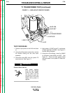
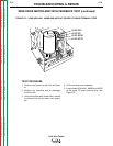

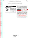
6. Apply 115 VAC power.
ELECTRIC SHOCK can kill.
• With power applied,
there are high voltages
inside the wire feeder.
Do not reach into the
wire feeder or touch any
internal part of the wire
feeder while power is
applied.
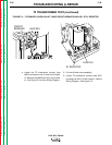
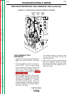
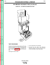
7. With the gun trigger activated or the gun ter-
minals jumpered together (see the Wiring
Diagram), check the motor armature volts at
leads #541(+) and #539(-). Normal is 5 to
95VDC depending on the wire feed speed
setting. As the armature voltage is increased
the wire feed speed should increase.
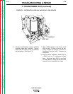
8. With the LN-9 at idle (gun trigger NOT acti-
vated), check the motor field voltage at
leads #626 and #627. Normal is 115VDC.
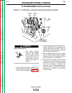
When the gun trigger is activated or the gun
terminals are jumpered together (see the
Wiring Diagram), the field voltage polarity
should reverse from the idle state. Normal is
115VDC, independent of motor speed.
9. If the above voltages are present and the
motor does not operate, the motor, motor
brushes or gear box may be faulty.
If the armature or field voltages are missing
or not correct, the power board or 1CR relay
may be faulty.
If the motor is running at high speed and the
armature voltage is high and uncontrollable,
proceed with the
Tach Feedback Test.
INSTALLATION
F-32 F-32
LN-9 Wire Feeder
Return to Section TOC Return to Section TOC Return to Section TOC Return to Section TOC
Return to Master TOC Return to Master TOC Return to Master TOC Return to Master TOC
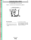
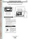
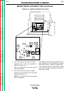
WIRE DRIVE MOTOR AND TACH FEEDBACK TEST (continued)
WARNING