


Return to Section TOC Return to Section TOC Return to Section TOC Return to Section TOC
Return to Master TOC Return to Master TOC Return to Master TOC Return to Master TOC
TROUBLESHOOTING & REPAIR
F-25 F-25
LN-9 Wire Feeder
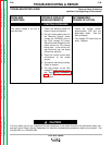
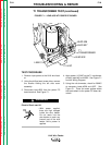
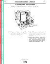
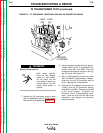
6. Using the volt/ohmmeter, check for 10VAC at
secondary leads #601 and #602. Typically,
these leads are yellow. Place the probes at
the lead splices. See Figure F.2.
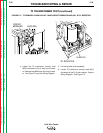
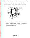
7. With 115VAC applied to the primary leads
#532 and #31, if either or both of the sec-
ondary voltages are missing or low the T1
transformer may be faulty. Replace the
transformer.
8. After the test is completed, disconnect the
115VAC from the T1 transformer primary
leads. Reconnect lead #532 to the power
PC board terminal. Close the left side cover
assembly and re-assemble the screws.
T1 TRANSFORMER TEST (continued)
FIGURE F.2 – SECONDARY LEADS #601 AND #602 AT LEAD SPLICES
LEAD 601
LEAD 602