


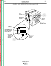
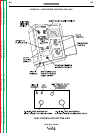
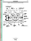
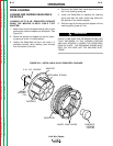

6. Loosen the ingoing guide tube clamping screw.
Install the all steel guide tube through the rear
brass block. Tighten the locking screw.
7. Replace the large ingoing guide tube into rear
brass block.
8. Install the outgoing guide tube with its plastic insert
through front brass block. Tighten the locking
screw so its dog point goes into the groove in the
O.D. of the guide tube.
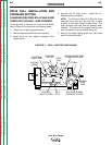
NOTE: The drive rolls and guide tubes are
stamped with the wire size ranges (in inches and
mm) for which they are designed. If a wire size
other than that stamped is to be used, the drive
rolls and guide tubes will have to be changed.
Drive rolls stamped with a "(C)" or "(H)" suffix to the
wire size range are recommended specifically for
use with cored wires.
SETTING THE IDLER ROLL SPRING PRESSURE
(2-ROLL WIRE DRIVES)
For Steel Wire, the idle roll pressure should be adjust-
ed as follows:
The idle roll pressure indicator should be set to the
proper wire size indication shown on the appropriate
"solid" or "cored" side of the idler roll spring pressure
nameplate. This setting is a starting point and may
have to be changed depending upon type of wire sur-
face condition, lubrication, and hardness.
The optimum idle roll setting can be determined when
there are wire stoppages. If the wire "bird nests"
between the drive roll and the guide tube, the idle roll
spring pressure is set too high. When set, during a
stoppage the drive rolls will slip. If the electrode is
removed from the cable there will be a slight waviness
in the electrode for about a foot beyond the slip marks
on the electrode. If there is no waviness, the pressure
is set too low.
For Aluminum Wire, the idle roll pressure should be
adjusted as follows:
1. With low idle roll pressure, load the feeder so it’s
ready for welding.
2. Run the feeder at a slow speed (about 100 IPM)
and reduce the idle roll pressure until the idler roll
stops rotating.
3. Slowly increase idle roll pressure until the idle roll
just starts to rotate consistently with the drive roll
without slippage, then add an extra 1/4 to 1/3 turn
more idle roll pressure.
This pressure setting should be optimum for feeding
and to avoid "bird-nesting" by allowing the drive roll to
slip on the wire if a gun cable jam or stoppage occurs.
If using harder or larger dia. aluminum wires, more idle
roll pressure, if necessary, can be tolerated. However,
if the pressure required to properly feed the aluminum
wire also permits "bird-nesting," or if excessive slip-
page results in aluminum pickup in the drive roll
groove, the loading on the wire by the gun-cable or
wire reel should be inspected and adjusted.
OPERATION
B-10 B-10
LN-9 Wire Feeder
Return to Section TOC Return to Section TOC Return to Section TOC Return to Section TOC
Return to Master TOC Return to Master TOC Return to Master TOC Return to Master TOC