


Return to Section TOC Return to Section TOC Return to Section TOC Return to Section TOC
Return to Master TOC Return to Master TOC Return to Master TOC Return to Master TOC
TROUBLESHOOTING & REPAIR
F-54 F-54
LN-9 Wire Feeder
PROCEDURE
1. Remove input power to the LN-9 wire feeder.
2. Lift the right side cover assembly.
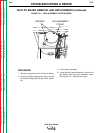
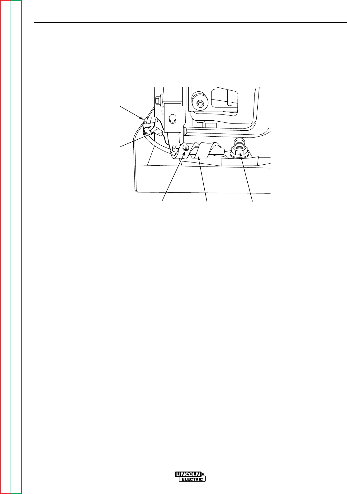
3. Locate the CR2 reed switch. See Figure
F-15.
4. With the 3/4" wrench, remove the bolt mount-
ing the copper reed switch energizer to the
conductor block. This step is optional, but it
makes disassembly easier on 4-roll models.
5. Using the slot head screwdriver, remove the
self-tapping screw holding the reed switch
into the copper energizer.
6. Locate and untape the splices from leads
#529 and #628 to the reed switch leads.
7. Using the slot head screw driver and 11/32"
wrench, remove the screws and nuts from the
lead splices. Note the position of the reed
switch in the energizer for reassembly.
8. Carefully slide the reed switch assembly from
the copper energizer.
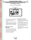
REPLACEMENT
9. Slide the reed switch into the energizer.
Position it according to step 7.
10. With the slot head screw driver and the
11/32" wrench, connect the #529 and #628
lead splices with the screws and nuts. Tape
the connections.
11. With the slot head screw driver, tighten the
self-tapping screw that holds the reed switch
to the copper energizer.
12. With the 3/4" wrench, mount the copper
energizer to the conductor block.
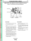
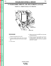
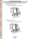
REED SWITCH (CR2) REMOVAL AND REPLACEMENT (continued)
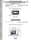
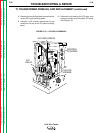
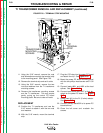
FIGURE F.15 – CR2 REED SWITCH LOCATION AND COMPONENTS
COPPER
ENERGIZER
3/4" BOLTSELF-TAPPING
SCREW
LEAD 628
LEAD 529