


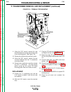
TROUBLESHOOTING & REPAIR
F-59 F-59
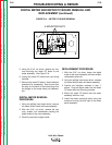
LN-9 Wire Feeder
Return to Section TOC Return to Section TOC Return to Section TOC Return to Section TOC
Return to Master TOC Return to Master TOC Return to Master TOC Return to Master TOC
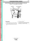
T1 TRANSFORMER REMOVAL AND REPLACEMENT (continued)
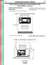
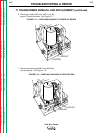
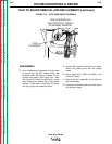
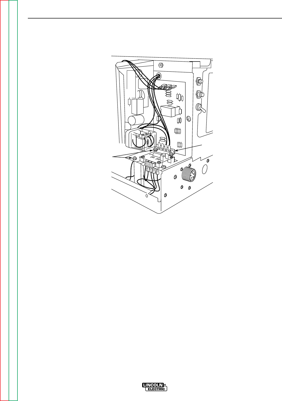
11. Using the 5/16" wrench, remove the nuts
and lockwashers mounting the terminal strip
to the mounting panel. See Figure F.20.
12. Remove the terminal strip and set it aside.
13. Using the 5/16" wrench, remove the two
nuts and washers from the T1 transformer
mounting screws.
14. Remove the transformer mounting screws
and the T1 transformer. This may require
gently prying up the control PC board
mounting panel. Be sure to clear all leads.
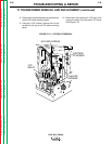
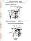
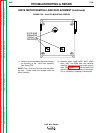
REPLACEMENT
15. Position the T1 transformer and use the
5/16" wrench to attach it with the two nuts
and washers.
16. With the 5/16" wrench, mount the terminal
strip.
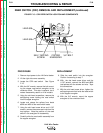
17. Plug the 1CR relay into the power PC board
and attach the clip. See
Figure F.19.
18. Mount the power PC board mounting panel
with the two phillips head screws and 11/32
nut.
19. Connect leads #601 and #602 at the lead
splices. See
Figure F.18.
20. Connect leads #526 AND #527 at their ter-
minals on the power PC board. See
Figure
F.17.
21. Solder lead #31 to the R1 (2 ohm) resistor.
See
Figure F.16.
22. Connect primary lead #532 to its power PC
board terminal.
23. Close the left cover and re-attach the
screws.
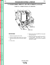
FIGURE F.20 – TERMINAL STRIP MOUNTING
T1
TRANSFORMER
MOUNTING
SCREWS
TERMINAL
STRIP