


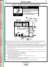
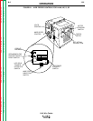
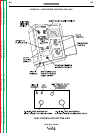
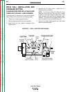

CONTROLS AND SETTINGS
Operator controls for LN-9N, NE, S and SE models are
shown in Figure B.1. Controls for LN-9F models are
shown in Figure B.2. Refer to these figures and the fol-
lowing descriptions of the controls.
ELECTRODE POLARITY SWITCH: The polarity
switch is located inside the wire drive section on the
LN-9 model and on the front panel of both the LN-9F
2-Roll and 4-Roll control box. Set the switch to the
same polarity as the electrode lead connection to the
power source. If the switch is not set for the correct
polarity, the wire feeder will stop welding shortly after
the arc is struck. See the topic
"Automatic
Shutdown"
later in this section of the manual.
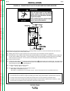
WIRE FEED DIRECTION SWITCH: The direction
switch is located inside the wire drive section on the
LN-9 model and on the front panel of both the LN-9F
2-Roll and 4-Roll control box. This switch permits the
wire to be fed in either direction when the trigger is
pressed or when using the cold inch switch feature of
the K202 Burnback kit. Be sure this switch is set for
forward feed when you are ready to weld.
HOT-COLD TRIGGER INTERLOCK SWITCH: This
switch is located on the front rail on the LN-9 model
and on the front panel of both the LN-9F 2-Roll and
4-Roll control box. The three-position switch serves a
dual purpose:
1. "Hot-Cold" Wire Feed - In the center position the
wire will be electrically cold when feeding with the
gun trigger. In either the up or down positions the
wire will be "hot" when feeding with the gun trigger.
2. Trigger Interlock Function - In the down position
the trigger interlock will be OFF, allowing the gun
trigger to function in the normal mode. This stops
wire feed and welding when the trigger is released.
In the up position the trigger interlock will be ON.
The trigger interlock feature functions as follows:
a) When you are not welding, the trigger will function
in the normal mode, which feeds only when the
trigger is closed.
b) Once the welding arc has been struck, the gun
trigger may be released. Welding will continue
until one of the following occurs:
• The arc is extinguished by quickly pulling the gun
away from the work.
or
• The trigger is again depressed and released.
OPERATION
B-4 B-4
LN-9 Wire Feeder
Return to Section TOC Return to Section TOC Return to Section TOC Return to Section TOC
Return to Master TOC Return to Master TOC Return to Master TOC Return to Master TOC