


Return to Section TOC Return to Section TOC Return to Section TOC Return to Section TOC
Return to Master TOC Return to Master TOC Return to Master TOC Return to Master TOC
TROUBLESHOOTING & REPAIR
F-33 F-33
LN-9 Wire Feeder
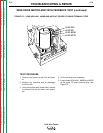
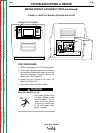
TACH FEEDBACK TEST
PROCEDURE
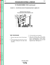
1. Locate tach PC board leads #510, #525 and
#555 on the control PC board. See Figure
F.7.
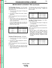
2. Check leads #525(+) to #510(-) for the pres-
ence of 15VDC. This is the supply voltage
from the control PC board to the tach PC
board. If the voltage is present, proceed to
the next step. If the voltage is missing,
check the wiring and perform the
General
Power Supply Test.
3. With gun trigger activated or the gun termi-
nals jumpered together (see the Wiring
Diagram), check leads #555(+) to #510(-) for
the presence of between 4.5 - 10.5VDC.
(The motor must be running). This is the
feedback voltage from the tach PC board to
the control PC board. This voltage is depen-
dent upon motor speed.
If the feedback voltage is missing or does
not vary with motor speed, the tach PC
board may be faulty.
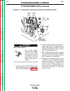
4. After the wire drive motor and tach feedback
tests are completed, remove the jumper
from the gun terminals (if used) and close
the left case side cover assembly and re-
attach the screws.
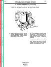
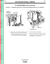
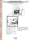
WIRE DRIVE MOTOR AND TACH FEEDBACK TEST (continued)
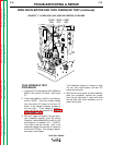
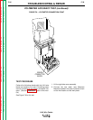
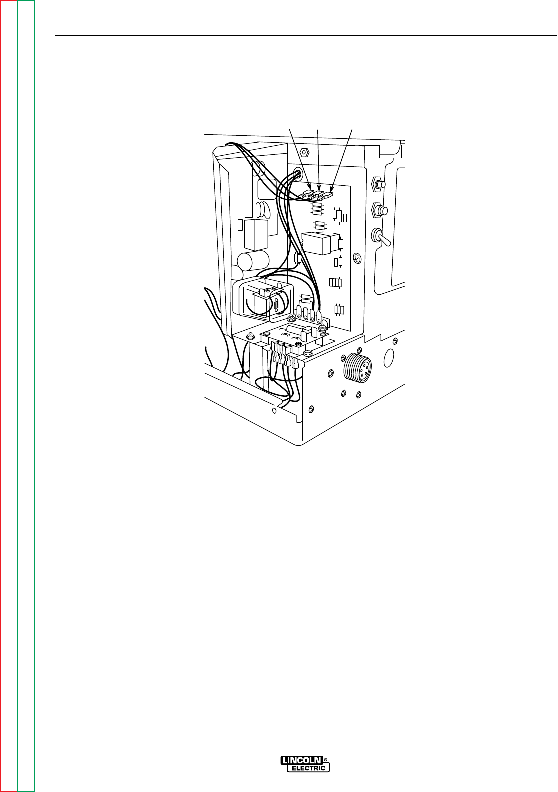
FIGURE F.7 – LEADS #525, #510, #555 ON CONTROL PC BOARD
LEAD
525
LEAD
510
LEAD
555