


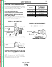


PRINTED CIRCUIT BOARD
FUNCTIONS
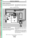
POWER BOARD
The input power (115VAC) is applied to the power
board, and from that the power board develops the DC
field voltage for the wire drive motor. The SCR circuit-
ry, used to control the motor armature voltage, is also
contained on the power board.
The relay used to activate motor armature voltage, field
voltage, auxiliary output on terminals 32A-7, and power
source output (#2 and #4) is housed on the power
board.
The rectified and regulated power supplies, used for
the LN-9 control circuitry, are incorporated in the power
board.
The shut down, start response and trigger interlock cir-
cuitry, in addition to the rectified and regulated power
supplies used for the LN-9 control circuitry, is included
in the power board design.
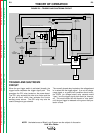
CONTROL BOARD
The control board provides a reference voltage to the
wire speed control and voltage control potentiometers,
allowing SET signals to be produced.
The control board also powers and processes the feed-
back signals from the tachometer board. It compares
the actual speed information to the SET speed com-
mand signal and develops firing pulses that drive the
motor armature SCR circuitry, located on the power
board.
Initial acceleration rates for wire feed speed are con-
trolled by the control board as well as the SET speed
and actual speed signals for the digital meter circuitry.
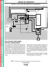
VOLTAGE BOARD
The voltage board compares the SET voltage values to
the actual voltage values and makes any necessary
correction by sending the appropriate signal to the
Lincoln CV power source. If for any reason the arc
voltage cannot be controlled to the SET voltage, the
voltage board interrupts the LN-9 trigger path, and the
unit shuts down. The response (Fast or Slow) to
changes in arc voltage is also controlled by the voltage
board, as well as the SET and actual arc voltage sig-
nals for the digital meter circuitry.
TRIGGER BOARD
The trigger transformer supplies 24VAC to the trigger
board where it is rectified and regulated to 20VDC.
This DC voltage is used in the gun trigger circuit to ini-
tiate the welding operation.
TACHOMETER BOARD
A square wave frequency signal, proportional to motor
speed, is generated by the tachometer board and sent
to the control board.
METER BOARD
The meter board contains signal scaling and power
supply circuitry for the digital meter.
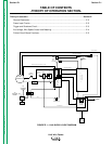
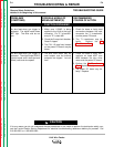
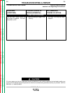
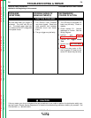
THEORY OF OPERATION
E-5 E-5
LN-9 Wire Feeder
Return to Section TOC Return to Section TOC Return to Section TOC Return to Section TOC
Return to Master TOC Return to Master TOC Return to Master TOC Return to Master TOC
NOTE: Unshaded areas of Block Logic Diagram are the subject of discussion.