


SAFETY PRECAUTIONS
ELECTRIC SHOCK can kill.
• Only qualified personnel should
perform this maintenance.
• Turn the input supply power
OFF at the disconnect switch or
fuse box before working on this
equipment.
• Do not touch electrically hot parts.
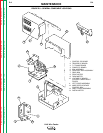
ROUTINE MAINTENANCE
DRIVE ROLLS AND GUIDE TUBES
After feeding any coil of wire, inspect the drive roll sec-
tion. Clean it as necessary. Do not use a solvent for
cleaning the idle rolls(s) because it may wash the lubri-
cant out of the bearing. The drive roll(s) and guide
tubes are stamped with the wire sizes they will feed. If
you use a wire size other than that stamped on the
rolls, the roll(s) and guide tubes must be changed.
The drive rolls using the knurled "V-groove" design
have a double set of teeth so they can be reversed for
additional life. Between the two knurled rolls for .068
through .120" is a shim washer which limits the dam-
age to the wire to a minimum should wire feeding prob-
lems occur. When drive rolls are interchanged, leave
the three socket head screws of the roll assembly
loose until it is re-assembled on the drive shaft. Then
tighten all three. Be sure the roll faces and spacer
faces are thoroughly cleaned before re-assembly.
Drive rolls for 1/16" and smaller solid electrodes using
the smooth "V-groove" design have no teeth. They are
not reversible.
See the
Operation
Section for drive roll installation
instructions.
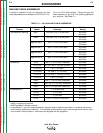
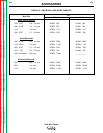
See
Table C.2
in the
Accessories
section for drive roll
and guide tube kits.
WIRE REEL MOUNTING - 50 AND 60 LB.
COILS
To prolong the life of the reel shaft, periodically coat it
with a thin layer of grease. No maintenance of the
brake assemblies is needed. If the brake shoe wears
through to metal, replace the brake assembly.
WIRE REEL MOUNTING - READI-REELS
AND 10 THROUGH 30 LB. SPOOLS
No routine maintenance required. Do not lubricate
the 2" spindle.
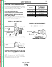
PERIODIC MAINTENANCE
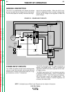
CONTROL BOX
Every six months open and inspect the control section.
The accumulated dirt should be gently blown off all of
the electrical components. See
Figure D.3
for compo-
nent locations. Be sure the air that is being used is dry.
Check the contacts of the large plug-in relay.
A spatter resistant shield protects the digital meter.
This shield must always be installed. If it breaks or
becomes damaged, replace it by removing the two
screws securing its frame, installing a new shield, and
reattaching the frame.
WIRE DRIVE MOTOR AND GEAR BOX
Every year examine the gearbox. Paint the gear teeth
with molydisulfide-filled grease such as Non-Fluid Oil
Corporation’s A-29 Special/MS Lubricant. Do not use
a graphite grease.
Check the motor brushes. Replace if they are worn
down to 1/4" or less. When ordering feed motor brush-
es, give all information from the motor nameplate.
MAINTENANCE
D-2 D-2
LN-9 Wire Feeder
Return to Section TOC Return to Section TOC Return to Section TOC Return to Section TOC
Return to Master TOC Return to Master TOC Return to Master TOC Return to Master TOC
WARNING