


F-65 F-65
LN-9 Wire Feeder
Return to Section TOC Return to Section TOC Return to Section TOC Return to Section TOC
Return to Master TOC Return to Master TOC Return to Master TOC Return to Master TOC
TROUBLESHOOTING & REPAIR
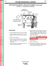
DRIVE MOTOR REMOVAL AND REPLACEMENT (continued)
PROCEDURE
1. Remove input power to the LN-9 wire feeder.
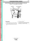
2. Using the phillips head screw driver, remove
the screws holding the left side cover assem-
bly.
3. Lift the cover assembly.
4. With the slot head screwdriver and the 3/8"
wrench, remove the R1 (2 ohm) resistor.
Note the position of the insulators for
reassembly.
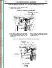
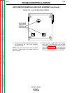
5. Using the Phillips head screwdriver remove
the 9 pin amphenol connector.
6. Set the resistor and the amphenol connector
aside as far as the lead lengths will allow.
This is necessary to gain access to one of
the three screws that mount the glastic base
to the floor assembly.
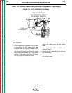
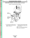
7. Remove the tach PC board and rotating
disc. (See the
Tach PC Board Removal
and Replacement
procedure).
8. Remove the two screws from the tach PC
board housing.
9. Remove the insulator.
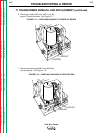
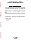
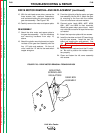
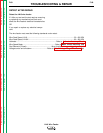
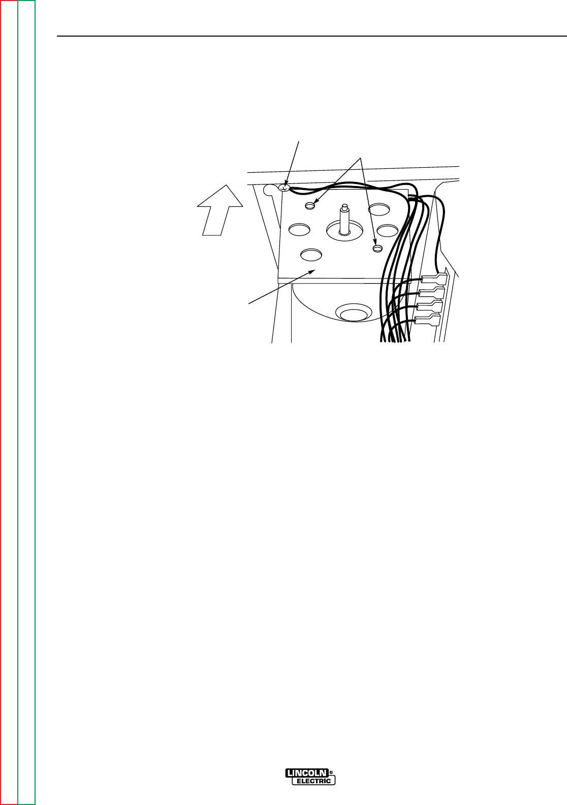
10. Remove the two screws from the top motor
plate and remove the plate. (Remove it from
the other side.) See Figure F.25.
FIGURE F.25 – TOP MOTOR PLATE SCREWS
SCREWS
MOTOR
GROUND LEAD
REMOVE FROM
OPPOSITE SIDE
TOP
PLATE