


DRIVE ROLL INSTALLATION AND
PRESSURE SETTING
CHANGING WIRE FEED ROLLS AND GUIDE
TUBES FOR TWO-ROLL
WIRE FEEDERS
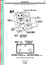
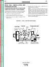
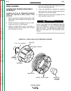
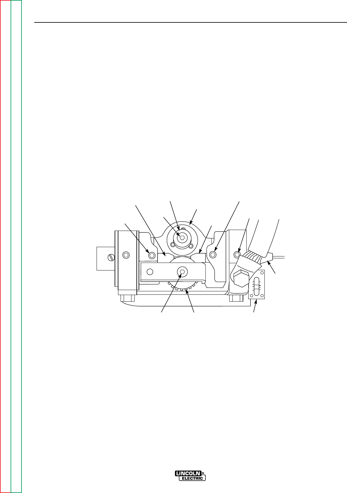
To change drive or idle rolls on a two-roll wire feeder,
refer to Figure B.3 and perform the following steps:
1. Loosen idle roll spring pressure screw.
2. Remove clamping collar from the drive shaft.
3. Install drive roll and replace clamping collar.
Tighten screw.
4. Remove idle roll shaft screw - install idle roll.
Replace screw and tighten.
NOTE: The Aluminum Wire Drive Roll Kits have
one-piece drive rolls and idle rolls with a larger
chamfer on one side, instead of gear teeth. This
larger chamfer side must face the gearbox when
installed. The side with the smaller chamfer and
wire size stencil must be installed facing out.
5. Remove the large ingoing guide from rear brass
block by loosening screw.
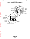
OPERATION
B-9 B-9
LN-9 Wire Feeder
Return to Section TOC Return to Section TOC Return to Section TOC Return to Section TOC
Return to Master TOC Return to Master TOC Return to Master TOC Return to Master TOC
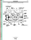
FIGURE B.3 – 2 ROLL WIRE FEED MECHANISM
CLAMPING
COLLAR
DRIVE
ROLL
IDLE ROLL
SHAFT SCREW
IDLE
ROLL
INGOING
GUIDE
TUBE
OUTGOING
GUIDE TUBE
GUIDE
TUBE
INGOING GUIDE TUBE
CLAMPING SCREW
SCREW
LOCKING
SCREW
SCREW
IDLE ROLL SPRING
PRESSURE SCREW