


Return to Section TOC Return to Section TOC Return to Section TOC Return to Section TOC
Return to Master TOC Return to Master TOC Return to Master TOC Return to Master TOC
TROUBLESHOOTING & REPAIR
F-24 F-24
LN-9 Wire Feeder
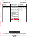
T1 TRANSFORMER TEST (continued)
TEST PROCEDURE
1. Remove input power to the LN-9 wire feed-
er.
2. Using the phillips head screw driver, remove
the screws holding the left side cover
assembly.
3. Disconnect lead #532 from the power PC
board terminal. See Figure F.1.
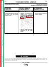
Electric Shock can kill.
• With power applied,
there are high voltages
inside the wire feeder.
Do not reach into the
wire feeder or touch any
internal part of the wire
feeder while power is
applied.
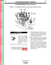
4. Apply power (115VAC) to the T1 transformer
primary leads #31 and #532. See Figure F.1
and the Wiring Diagram.
5. Using the volt-ohmmeter, check for 28VAC
at secondary leads #526 and #527. See
Figure F.1. Place the meter probes where
the leads attach to the power PC board ter-
minals.
WARNING
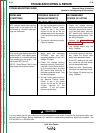
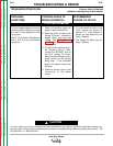
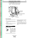
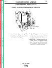
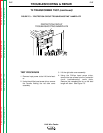
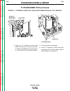
FIGURE F.1 – LEAD #532 AT POWER PC BOARD
115 VAC
T1
TRANSFORMER
LEAD 526
LEAD 532
LEAD 31
LEAD 527