


Return to Section TOC Return to Section TOC Return to Section TOC Return to Section TOC
Return to Master TOC Return to Master TOC Return to Master TOC Return to Master TOC
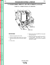
TROUBLESHOOTING & REPAIR
F-52 F-52
LN-9 Wire Feeder
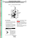
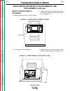
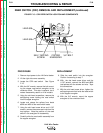
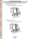
FIGURE F.14 – METER PC BOARD REMOVAL
4 MOUNTING NUTS
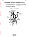
DIGITAL METER AND METER PC BOARD REMOVAL AND
REPLACEMENT (continued)
5. Using the 5/16" nut driver, remove the four
nuts mounting the meter PC board to the
meter assembly. See Figure F.14.
6. Unplug the meter PC board from the wiring
harness.
7. Remove the meter PC board. Note insulation
placement for reassembly. Also be sure that
the plug on the back of the board plugs into
the prongs on the meter when you reassem-
ble.
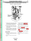
DIGITAL METER REMOVAL
PROCEDURE
1. Using the phillips head screw driver, remove
the meter shield frame and bezel assembly.
2. With the 5/16" nut driver, remove the two
nuts, screws, and lockwashers holding the
digital meter to the cover assembly.
3. Carefully remove the digital meter.
REPLACEMENT PROCEDURE
1. With the 5/16" nut driver, fasten the digital
meter to the cover assembly with two screws,
lockwashers and nuts.
2. Using the phillips head screw driver, reattach
the meter shield frame and bezel assembly.
3. Position the insulation removed in step 7,
above. Plug the digital meter into the meter
PC board and into the wiring harness.
4. Mount the meter PC board onto the meter
assembly with four nuts.
5. Install the meter enclosure panel using two
screws at the top left and right of the meter
panel assembly.