


TROUBLESHOOTING & REPAIR
F-67 F-67
LN-9 Wire Feeder
Return to Section TOC Return to Section TOC Return to Section TOC Return to Section TOC
Return to Master TOC Return to Master TOC Return to Master TOC Return to Master TOC
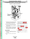
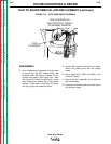
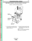
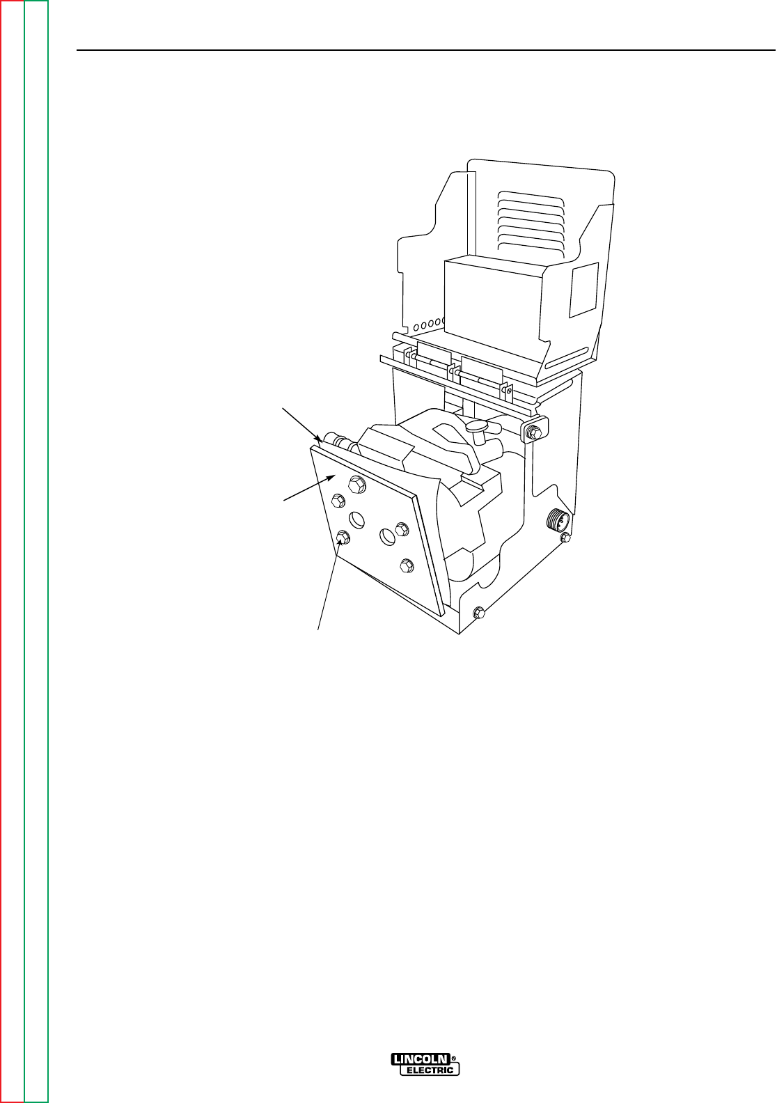
13. Lift the right side cover assembly and care-
fully lift and slide the motor and wire drive
assembly partially out of the LN-9 box
assembly. See Figure F.27.
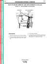
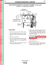
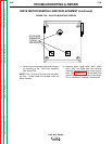
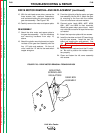
14. Using the 1/2" wrench, remove the four bolts
and associated washers holding the glastic
mounting board and mylar insulator to the
gear box assembly.
NOTE: Four-roll drive units will require the
removal of a 1/2" bolt mounting the reed switch
copper energizer to the glastic plate.
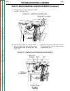
FIGURE F.27 – MOTOR AND WIRE DRIVE REMOVAL
GLASTIC
MOUNTING
BOARD
MYLAR
INSULATOR
MOUNTING
BOLTS (4)
DRIVE MOTOR REMOVAL AND REPLACEMENT (continued)