


7... HYPERNET™ ICON BASED PROGRAMMING
USING THE OMP-MODL7-8
TERMINALS
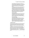
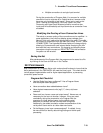
All icons (except the Global Icon) have terminals for the addition
of signal connections. An explanation for the various types of
terminals follows:
LOGIC / DATA INPUT TERMINALS
On the left side of the icon are typically one or two inputs for
Logic or Data signal types. Data enters the icon for
processing through these Input terminals. Some two input
icons (eg Math) do not require signals to be connected to
both Input terminals for operation.
LOGIC / DATA OUTPUT TERMINAL
On the right side of the icon is a single Output terminal.
After processing of an input signal(s) is completed, the
output is updated. Depending on the type of icon and the
User configuration, this Output terminal may or may not be
updated every time the Update and/or an Input terminal is
updated. The Enable input (description follows), the type of
processing that the icon performs, and User specified
parameters within the Configuration dialog all effect when
the Output terminal is updated.
For example, when using an Average icon, the Output
terminal will only be updated with a new value after a User
specified number of inputs have been averaged.
ENABLE INPUT TERMINAL
Many icons have an Enable input terminal located near their
top left corner that will accept a Logic input (True/False).
Depending on the state of the input signal, the icon is
enabled or disabled for processing.
NOTE: if the Enable input is not connected, it
defaults to the Enabled state.
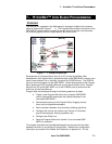
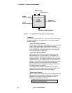
UPDATE Input
ENABLE Input
OUTPUT of
DATA or LOGIC
OUTPUT of UPDATE SIGNAL
X Input
DATA or LOGIC
Y Input
DATA or LOGIC
Icon
Graphic
ML128
Figure 7... -10: HyperNet Icon topology and terminal types