


11.. . APPENDIX A: MASTER ICON FILE REFERENCE
USING THE OMP-MODL11-42
MEMORY (OMP-MODL) ICON
FUNCTION:
The Memory icon represents data memory within the OMP-MODL System Base (either
internal or a PCMCIA memory card if installed).
The Units associated with the icon Output connected to the Memory icon Input will be
stored with the recorded values.
INPUTS:
Data/Logic Signal: Data or Logic type. The terminal will accept either signal type.
Update Clock: None
Enable: Processing of icon is allowed when Enable pin is unconnected or
when connected and Enable signal is TRUE.
OUTPUTS:
Output Signal: Hardware output to memory only. No output terminal shown on
icon for Program Net connections.
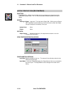
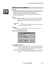
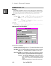
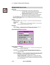
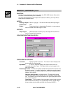
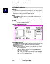
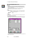
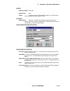
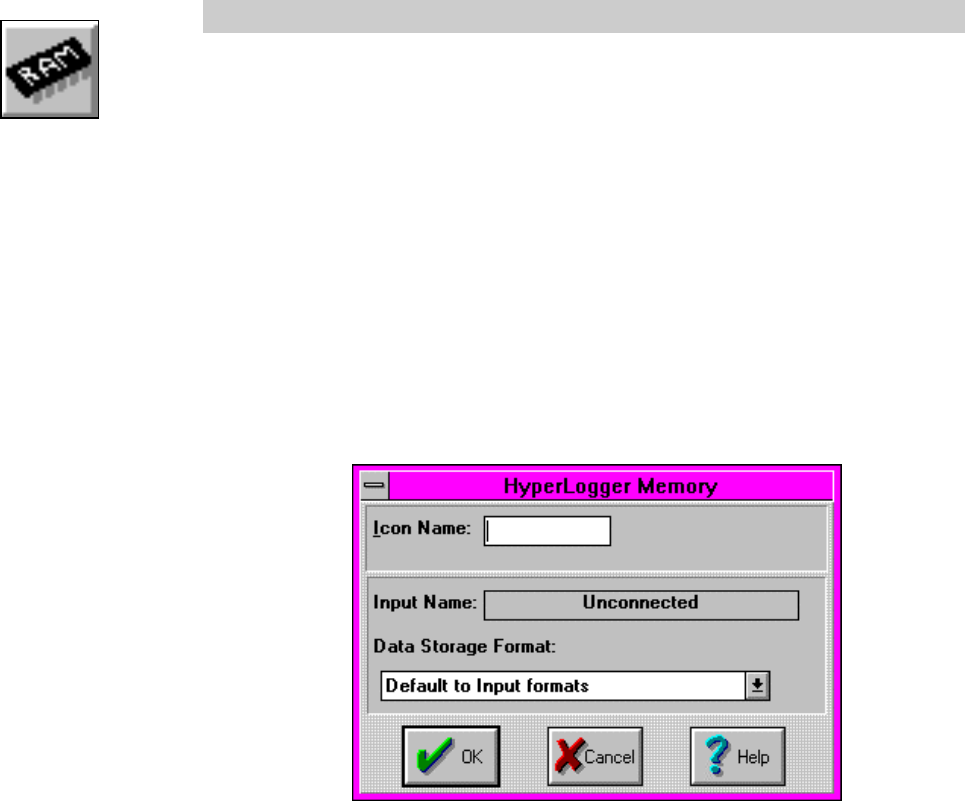
ICON CONFIGURATION DIALOG BOX:
CONFIGURATION OPTIONS:
Icon Name: Specify the label for the icon. This name will show directly under
the icon within the Program Net.
Input Name: In this box, HyperNet displays the Output Name of the icon
connected to this icon’s Input. The Output Name can be changed in the
other icon’s dialog.
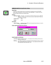
Data Storage Format: The User can specify the data format that will be used to store
the data in memory. In certain applications, additional processing speed
and/or less memory per stored sample can be realized through a judicious
selection of the format.
Default to Input Formats - the default format. The data will be stored
using the same data format (Floating Point or Long Integer) as the Inputs
use. This selection can be used consistently with good speed performance
and no loss of precision.
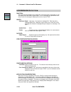
Long Integer - The Input data will be converted to integer format, then the
data will be stored to memory in a signed Integer format. Signed Integer
format includes only the digits to the left of the decimal (XXXXX.)