


3... INTERFACE MODULES
USING THE OMP-MODL 3-3
alignment and connection with the mating module. If any pins
are bent, straighten them with a small pliers.
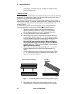
3. Orient the Interface Module to be added so that the similar
length connector bus’s align and the terminal strips or other User
controls are all at the same end.
4. While peering into the gap between the modules, carefully
match up the connector pins on one module and the mating
socket on the other module and slide the two together. Examine
the connectors from different views as the modules come
together to insure that all of the pins are properly aligned.
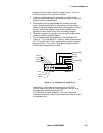
5. Press the modules firmly together and reinstall the side access
screws to hold the modules together.
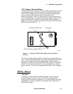
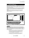
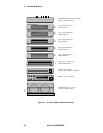
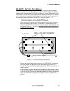
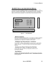
1. Turn the logger power ON and observe the Feedback LED
(Figure 3... -3) on the MLCPU-1 module. Within a few seconds,
the LED should blink 5 times indicating that a system reset has
been performed. This is also a fairly good indication that the
unit has been reassembled correctly.
Alternatively, if the logger is equipped with the ML-DISP
module, observe the LCD for normal operation and any error
messages afer switching the power ON.
If an indication of proper operation is not seen, repeat the
installation procedure, examining connector pins closely for bent
or misaligned pins.
STOP
RESET
ENABLE
POWER
SERIAL PORT
RELAY R2
RELAY R1
STATUS
FEEDBACK
EXTERNAL POWER
RELAY R1
RELAY R2
+5V
TTL ALARM OUTPUT
GND
1 2 3 4 5 6 7 8 9
ML004
Figure 3... -3: Feedback LED on MLCPU-1