


3... INTERFACE MODULES
USING THE OMP-MODL3-42
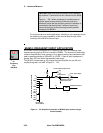
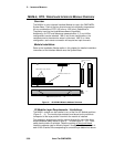
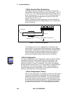
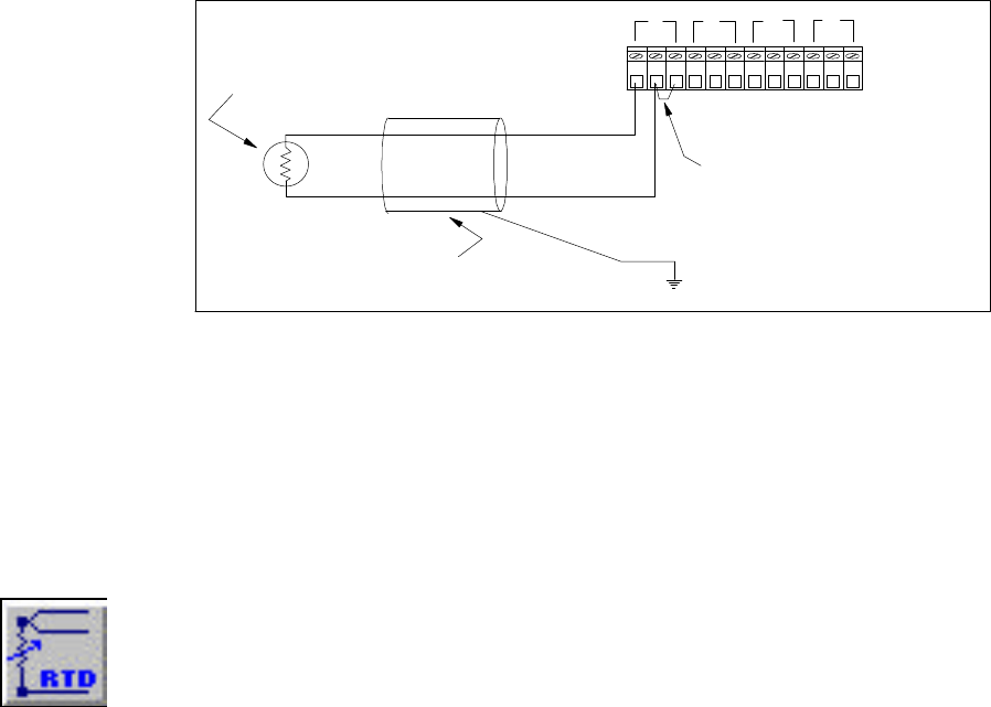
2-Wire Terminal Strip Connections:
The MLIM-4 module is provided with a 12 position terminal strip.
Each MLIM-4 input channel utilizes 3 of the 12 terminals (1-2-3, 4-5-
6, 7-8-9, 10-11-12). Connect the input signal to the first two of the
three input terminals (1-2, 4-5, 7-8, 10-11) on the terminal strip. A
wire jumper must then be installed from the second to the third
terminal (2-3, 5-6, 8-9, 11-12).
Refer to Chapter 6 for steps to generate a Terminal Strip Wiring
printout after construction of a Program Net for use in making field
wiring connections.
For long lead wire runs and in applications in electrically noisy
environments, it is recommended that twisted pair and/or shielded
wire be used. If shielded wire is used, the shield at the OMP-MODL
end should be connected to an external earth ground (Figure 3... -
28) or if available, a grounded Shield connection provided on
another type installed interface module (such as the MLIM-1).
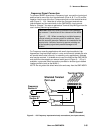
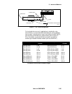
3-Wire Configuration
The 3-wire configuration is used in applications where the lead wire effects
calculated as above will have a significant error inducing effect on the
resistance measurement. The 3-wire configuration requires two input
channels (A and B or C and D) to implement. From within the HyperNet
Window, double-clicking Channel A or C icons displays a dialog and allows
for selection of 2, 3, or 4-wire connection. When 3 -wire is selected, a
second corresponding icon (Channel B or D) is removed as this second
channel is required for the 3 -wire measurement.
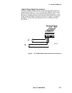
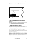
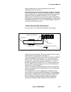
3-Wire Compensation Theory:
With a 3-wire configuration, the resistance of one of the lead wires is
measured, doubled and then subtracted out of the measured total
element plus lead wire circuit resistance. The 3-wire configuration,
as the name implies, requires the use of three discrete wires from
the module terminal strip to the element. Two of the leads connect
to one common end of the element and the other lead connects to
the other end of the element. The 3-wire configuration provides
21 1211109876543
RTD Element
Cable Shield
Jumper
A
B
C
D
Connect Shield to an Earth Ground
ML125
Figure 3... -28; 2-Wire Configuration
3-Wire
Config