


3... INTERFACE MODULES
USING THE OMP-MODL3-44
4-Wire Configuration
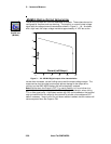
The 4-wire configuration is used in applications where the lead wire effects
calculated as above will have a significant error inducing effect on the
resistance measurement. The 4-wire configuration provides the best
compensation for lead wire resistance at the expense of running a 4th lead.
The 4-wire configuration requires two input channels (A and B or C and D) to
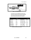
implement. From within the HyperNet Window, double-clicking Channel A
or C icons displays a dialog and allows for selection of 2, 3, or 4-wire
connection. When 4-wire is selected, a second corresponding icon (Channel
B or D) is removed as this second channel is required for the 4-wire
measurement.
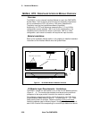
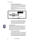
4-Wire Compensation Theory:
With a 4-wire configuration, the excitation current flows to and from
the element through one pair of leads. The actual voltage
developed across the element is then measured using a second pair
of Sense leads that conduct a very small amount of current (hence
adding negligible I * R voltage measurement error) .
The 4-wire configuration, as the name implies, requires the use of
four discrete wires from the module terminal strip to the element.
Two of the leads connect to one end of the element and the other
two to the other end of the element.
Due to the fact that the excitation current flows through a separate
pair of leads, wire gauge, temperature effects, and connection
resistance has no effect on the accuracy of the readings. The
Sense leads (connected to terminals 4-5 or 10-11) can be of lighter
gauge if desired as a very low current flows through them.
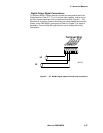
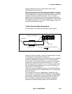
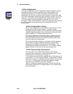
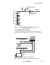
4-Wire Terminal Strip Connections:
As can be seen in the 4-Wire Wiring Diagram, each channel
requires 6 of the 12 terminals. Channel A uses terminals 1 through
6, and Channel C uses terminals 7 through 12.
The Excitation wires connect from opposite ends of the element and
to terminals 1-2 or 7-8 on the terminal strip. A second pair of Sense
wires then connects from opposite ends of the element to terminals
4-5 or 10-11. A wire jumper must then be installed connecting
terminals 2-3 for Channel A and 8-9 for Channel C.
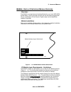
Refer to Chapter 6 for steps to generate a Terminal Strip Wiring
printout after construction of a Program Net for use in making field
wiring connections.
4-Wire
Config