


11.. . APPENDIX A: MASTER ICON REFERENCE
USING THE OMP-MODL 11-3
APPENDIX A: MASTER ICON REFERENCE
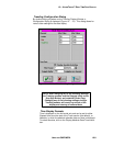
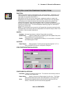
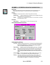
THERMOCOUPLE INPUT ICON:
FUNCTION:
Performs the thermocouple channel selection, amplification, cold junction compensation
and A-D conversion for a thermocouple hardware input from an MLIM-1 Interface Module.
The CJC reading is taken from the integral thermistor located by the terminal strip header
on the inside of the MLAD-1.
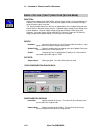
INPUTS:
Hardware: No signal input shown on Net for Program Net connections.
Update Clock: Output is updated with new reading upon each Update Clock pulse
when Enable input is unconnected or Hi.
Enable: Processing of icon is allowed when Enable pin is unconnected or connected
and Enable signal is TRUE.
OUTPUTS:
Output Signal: Data type signal. The Units of the output are degrees C or F,
selectable from the icon configuration dialog box.
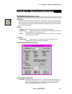
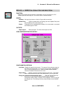
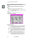
ICON CONFIGURATION DIALOG BOX:
CONFIGURATION OPTIONS:
Icon Name: Specify the name for the channel. This name will show directly under the
icon within the Program Net. If no name is User provided, the Backplane
Port (1 to 6) and Channel (A to D) where the actual Interface Module
channel is installed will be used for the name.