


11.. . APPENDIX A: MASTER ICON REFERENCE
USING THE OMP-MODL 11-7
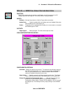
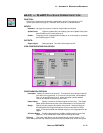
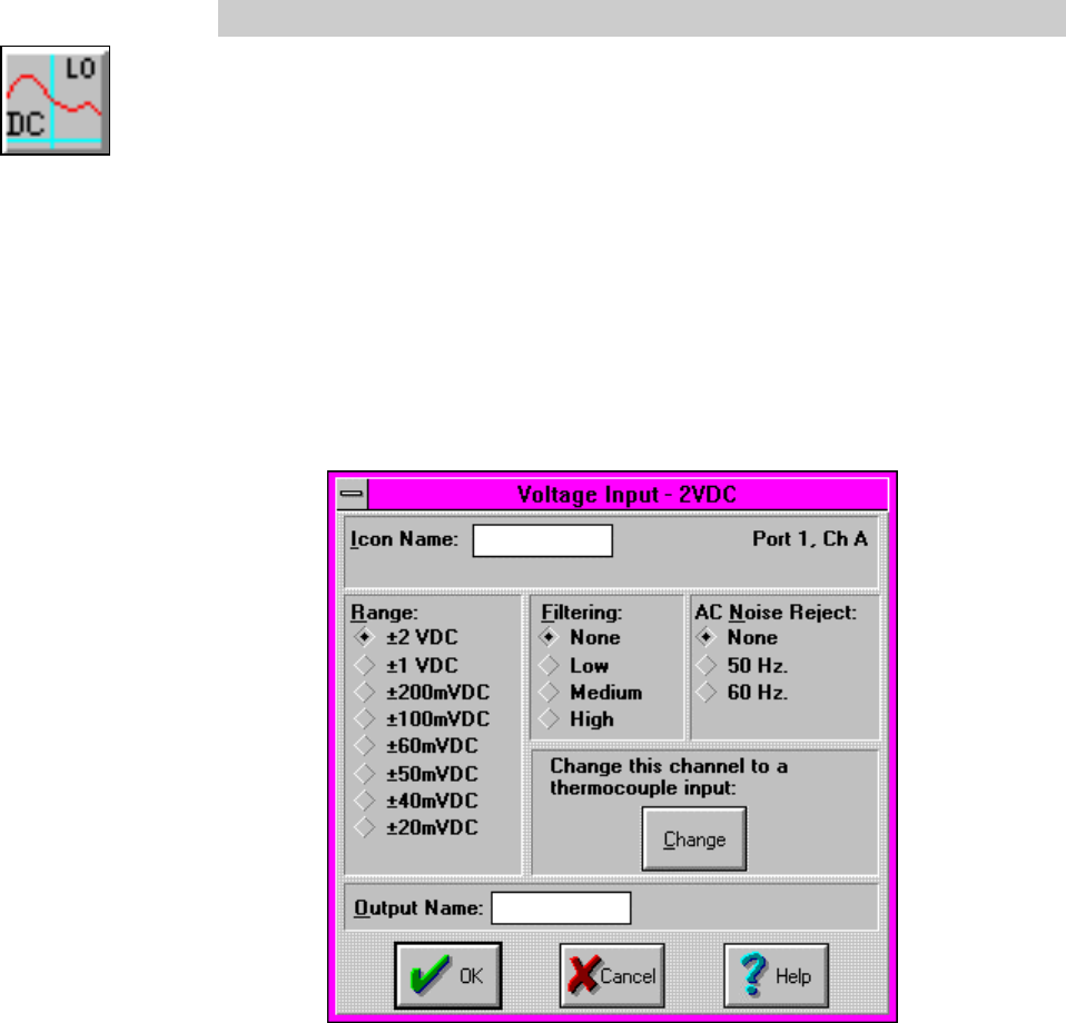
DC-LO; +/- 2VDC FULL SCALE VOLTAGE INPUT ICON
FUNCTION:
Performs the analog channel selection, amplification, and A-D conversion for a DC
voltage input within the range of +/-2V from an MLIM-1 Interface Module.
INPUTS:
Hardware: No signal input shown on Net for Program Net connections.
Update Clock: Output is updated with new reading upon each Update Clock pulse
when Enable input is unconnected or Hi.
Enable: Processing of icon is allowed when Enable pin is unconnected or connected
and Enable signal is TRUE.
OUTPUTS:
Output Signal: Data type signal. The Units of the output are Volts.
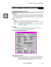
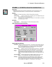
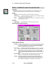
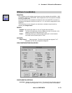
ICON CONFIGURATION DIALOG BOX:
CONFIGURATION OPTIONS:
Icon Name: Specify the name for the channel. This name will show directly under the
icon within the Program Net. If no name is User provided, the Backplane
Port (1 to 6) and Channel (A to D) where the actual Interface Module
channel is installed will be used for the name.
Output Name: Specify a name for the Output signal from this icon. This Output
Name will be referenced by other icons downstream in the Program Net.
Change this channel to a thermocouple input: Both the Thermocouple Icon
and the DC-LO Icon utilize the same Interface Module hardware
Configuration Switch setting. Because of this capability, a DC-LO Icon can
be changed into a Thermocouple Icon by simply clicking on the CHANGE
button.