


3... INTERFACE MODULES
USING THE OMP-MODL 3-25
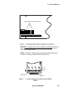
Thermocouple Application Notes:
Cold Junction Compensation (CJC): For thermocouple measurements,
the temperature of the terminal strip connections is required in the voltage to
temperature conversion equation used by the OMP-MODL. This
temperature is measured by the CJC sensor located in the MLAD-1 module.
Any differential temperature from the metal terminal strip connections to the
CJC sensor on the MLAD-1 circuit board will result in direct measurement
errors.
The MLAD-1 is thermally designed to provide good CJC sensor vs terminal
strip temperature tracking however, to minimize this potential error, avoid
installations or effects that will induce extreme temperature differential. The
most accurate readings will be achieved when the OMP-MODL has been
allowed to temperature stabilize. In rapidly changing temperature
environments, additional accuracy can be achieved if the OMP-MODL is
housed within another enclosure providing better temperature equalization
throughout the system.
DIFFERENTIAL POTENTIAL: to minimize current loop induced errors, use
isolated type thermocouples (ie thermocouples that are not in electrical
contact with a conductive surface to which they are attached) or insure that
all thermocouple junctions are at ground potential. Insure that input voltages
do not exceed 3.0V above or below circuit ground (maximum common mode
voltage).
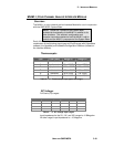
MLIM-1; DC VOLTAGE APPLICATION
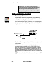
The MLIM-1 can support three different major ranges (and a multitude of sub-
ranges) of analog DC voltage input depending on the channel’s hardware
Configuration Switch setting (See Table 3... -4). To utilize an MLIM-1 channel as a
DC Voltage input, set that channel’s Configuration Switch per the Table for the
desired input signal range.
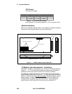
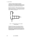
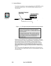
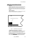
As shown in Figure 3... -12, when DC-MED or DC-HI are selected with the hardware
Configuration Switches, front-end divider circuitry is enabled. This circuitry
attenuates the input signal to a range that can be handled by the MLIM-1
instrumentation amplifier section.
TIP: For best accuracy and absolute resolution, utilize
the lowest range possible that will cover the input signal’s
dynamic range without over-ranging.
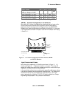
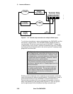
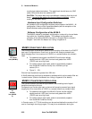
Signal Connection (all Ranges):
Interface Module channels configured as VDC inputs provide three terminal
strip connections per input; Positive lead, Negative lead, and Shield.
Connect the VDC signal positive and negative leads to the correct pair of
terminals on the module terminal strip (Figure 3... -15). Refer to Chapter 7
for steps to generate a Terminal Strip Wiring printout for use in making field
wiring connections.
Observe polarity or the output signal will be reversed.
VDC- Lo
Range Icon
VDC-
Medium
Range Icon