


11.. . APPENDIX A: MASTER ICON REFERENCE
USING THE OMP-MODL 11-85
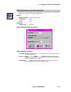
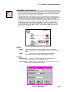
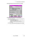
WARM-UP FUNCTION ICON
The Warm-up icon is is a special two Output terminal icon. It immediately outputs a logic
signal on one terminal upon receipt of an Update signal, then after a User programmed
delay, passes the Update signal to its second Output.
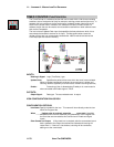
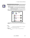
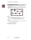
The typical application for the Warm-Up icon is to provide control of a power supply for
excitation of a sensor or transmitter and a short delay until the sensor/transmitter is read.
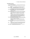
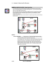
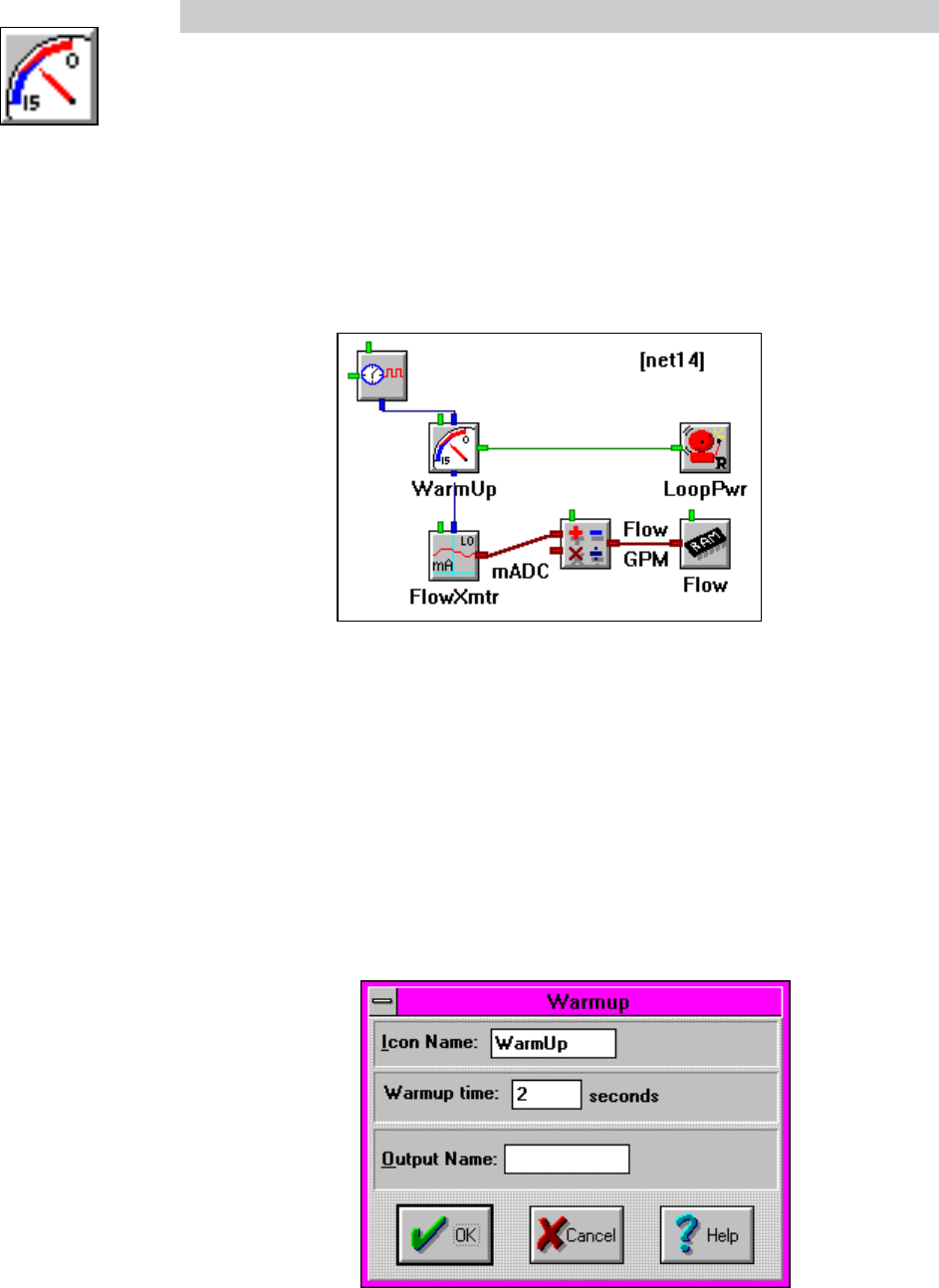
The following example Net illustrates that application. Upon receipt of the Update
command from the Sample Rate Clock, the Warm-up icon immediately cycles its Logic
Output terminalTrue which turns on the connected Relay Alarm icon to power up a
24VDC power supply for the 4-20mA loop excitation. The icon then waits for a User
defined period of time, then passes the Update command to the connected mA-Lo (4-
20ma) Input icon which then takes a sample. The next time the Net is executed, the
power supply is turned OFF.
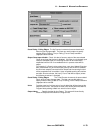
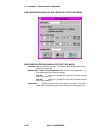
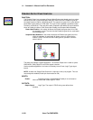
INPUTS:
Update: The icon immediately turns its Logic Output True when an Update
command is received. The Output staysTrue until the User provided time
expires.
Enable: Processing of the icon is allowed when the Enable pin is
unconnected or when connected and Enable signal is TRUE.
OUTPUTS:
Output Signal 1: Logic type. The Logic Output turnsTrue and staysTrue
immediately after receipt of an Update command.
Output Signal 2: Update type. The Update command is passed through the icon
after a User defined delay (warm-up time).