


2... OMP-MODL System Base
Using the OMP-MODL
2-9
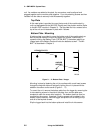
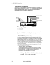
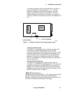
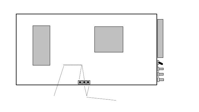
To change the setting, access must be gained to the jumper on
the top of the MLCPU-1 module (Figure 2... -5). Per the
assembly / disassembly instructions in Chapter 3, open the
logger to gain access to the top of the MLCPU-1. The Hi/Lo
jumper is installed on two pins of a 3 pin header. To program a
new range, remove and reinstall the jumper on the desired pair of
pins.
OVERVOLTAGE PROTECTION:
The MLCPU-1 incorporates circuitry to protect the logger from
over-voltage, transient voltage spikes, and over-current
conditions encountered on the External Power Terminals. In the
event that extended out of spec voltages are impressed on the
External Power terminals, protective circuitry will activate and
blow the 1.5A input fuse. Replacement fuses (P/N: Littelfuse
27301.5) are available from Omega Engineering Incorporated or
electronic distributors.
BATTERY CONNECTION PIGTAIL:
The MLCPU-1 is equipped with a pigtail and connector for
connection to the ML-BATT battery pack module. This connector
dangles from the bottom side of the MLCPU-1 circuit board. If
batteries are not utilized, this pigtail should be left unconnected.
Details on connection and use are provided in the section on the
ML-BATT battery module in Chapter 3.
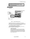
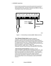
Relay R1 (Terminals 3 & 4)
Wiring connections for Output Relay 1. The relay is a normally open
device with contacts rated for 500 ma MAX at 32VDC MAX .
Operation is dependent on logic associated with the Relay Alarm #1
icon within the Program Net executing in the logger.
EPROM
CPU
LOW RANGE
HIGH RANGE
ML005
Figure 2... -5: MLCPU-1 External Power Voltage Range Jumper