


3... INTERFACE MODULES
USING THE OMP-MODL3-38
MLIM-4; RTD / RESISTANCE INTERFACE MODULE OVERVIEW
Overview
The MLIM-4 is a four channel Interface Module for use in the OMP-MODL
System Base. Each of the four channels can be individually programmed
for any combination of RTD (100 ohm or 1000 ohm), Resistance or
Thermistor input via the HyperWare software (HyperNet).
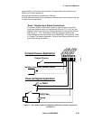
Additionally, for RTD and resistance measurements, 2, 3, and 4-Wire
configurations can be selected. With 3 and 4-wire configurations, the
resistance due to the extension wires is minimized. With 3 or 4-wire
configuration, each sensor connection will require two input channels.
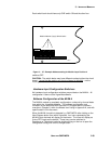
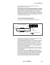
Module Installation:
Refer to the Installation Section earlier in this chapter for detailed installation
instructions of the Interface Module onto the System Base.
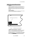
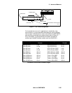
I/O Module Layer Requirements / Limitations:
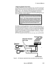
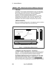
The MLIM-1 module can be installed in any of the five I/O Module positions
(Figure 3... -4). The module layer address must be set on the module to
correspond to the layer position into which the module is installed.
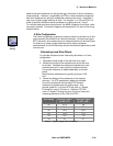
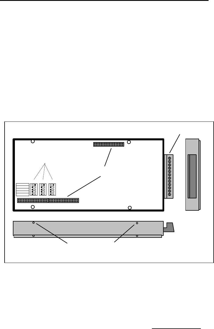
This address is programmed into the module through the use of the three
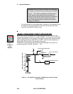
Module Address Switch banks (Figure 3... -26 and Figure 3... -27). Each
switch bank contains 5 switches. Note the marking on the circuit board
identifying address rows for Module Layers 2 through 5. Set one switch in
each of the 3 banks ON corresponding to a module layer determined above.
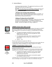
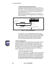
Inter-Module Connection bus
I/O Wiring Terminal
Strip
Side Retaining Screw holes
ml051
Module 3
Module 2
Module 4
Module 5
Module 6
OFF - ON OFF - ON OFF - ON
Module Address (Layer) Switches
Figure 3... -26: MLIM-4 Module Address Switches