


11.. . APPENDIX A: MASTER ICON REFERENCE
USING THE OMP-MODL 11-37
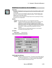
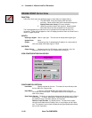
DIGITAL OUTPUT ICON (MLIM-2)
FUNCTION:
Four channels of Digital output are provided (along with 4 channels of Event / Counter/
and Frequency input) with the MLIM-2. With the MLIM-2 installed in a OMP-MODL, these
respective function icons become available for use in Program Nets.
The Digital Output icons provide software access to these digital outputs.
Refer to the Frequency, Counter and/or Event applications of the MLIM-2 for further
information on those functions.
INPUTS:
Data/Logic Signal: Logic type. True input turns hardware output ON. False input
turns output OFF. Optionally, use the Latch icon in front of the Digital
Output icon to latch the Output True upon receipt of a momentary True
input.
Update Clock: None
Enable: Processing of icon is allowed when Enable pin is unconnected or
connected and Enable signal is TRUE.
OUTPUTS:
Output Signal: Hardware output only. No output terminal shown on icon for
Program Net connections.
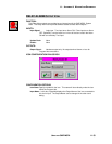
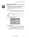
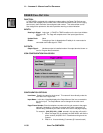
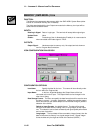
ICON CONFIGURATION DIALOG BOX:
CONFIGURATION OPTIONS:
Icon Name: Specify the name for the channel. This name will show directly under the
icon within the Program Net. If no name is User provided, the Backplane
Port (1 to 6) and Channel (A to D) where the actual Interface Module
channel is installed will be used for the name.
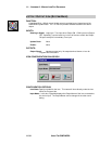
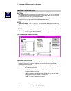
Input Name: In this box, HyperNet displays the Output Name of the icon connected to
this icon’s Input. The Output Name can be changed in the other icon’s
dialog.