


3... INTERFACE MODULES
USING THE OMP-MODL3-2
plastic bags. Anti-Static bags are available for storage of static
sensitive components.
INSTALLATION
When shipped, Interface Modules are provided with side screws and any necessary
accessories. If ordered with a logger, the Interface Modules are typically factory
installed in the System Base before shipment.
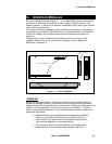
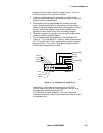
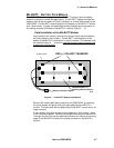
The Interface Modules stack onto the System Base building a `layered’ logger to
meet the User’s needs. All modules (except the ML-BATT Battery Pack) have an
inter-module connection bus that connects signals and power between the
modules(Figure 3... -1).
To add a module, perform the following steps and any special Installation
Instructions detailed in the following Interface Module specific sections.
1. Review the Interface Module instructions and observe any
special installation instructions. These may include setting
Module Address Switches and Input Configuration Switches.
2. Turn the OMP-MODL System Power switch OFF.
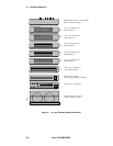
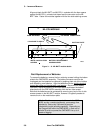
3. Determine the Port (layer) at which the new Interface Module is
to be installed. Refer to Figure 3... -4. Note that some modules
must be installed at a particular position (eg the MLIM-5 must be
installed between the MLCPU-1 and the MLAD-1 modules).
Also note that many modules require a Module address to
be programmed through the setting of one or more Module
Address Switches. This is covered in detail in the module
specific sections that follow.
4. Remove the four side retaining screws (Figure 3... -1) from the
enclosure nearest the joint into which the new module is to
added.
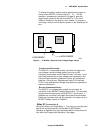
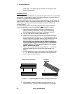
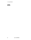
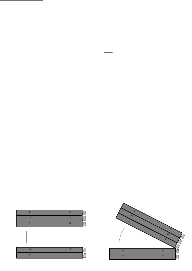
1. Carefully separate the layers while keeping them parallel (Figure
3... -2). Minimize the amount of twisting or rocking as this will
result in bent connector bus pins.
2. After separation, examing the gold connector bus pins on the
Interface Module. These pins must be straight to insure proper
CORRECT MODULE SEPERATION
INCORRECT
ML011
Figure 3... -2: Separating Modules without bending connector pins...