


11.. . APPENDIX A: MASTER ICON REFERENCE
USING THE OMP-MODL 11-21
COUNTER INPUT ICON (GPDI)
FUNCTION:
The GPDI (General Purpose Digital Input) is a hardware digital input for Event and
Counter applications and is incorporated into every OMP-MODL System Base.
As a COUNTER input, it accumulates counts from a User connected hardware signal
input, then outputs the count when it receives an Update command. When the count is
output, the counter is automatically set back to 0 and counting resumes.
The GPDI Counter (in contrast to the MLIM-2 Counter) is very fast and can count pulses
received at input rates up to 10 KHZ. However, when using the GPDI Counter with high
speed inputs, it is imperative that the Counter receive an Update command before it
counts up to 65,535 or a counter roll-over condition will occur and count data will be lost.
INPUTS:
Hardware: No signal input shown on Net for Program Net connections.
Update: The accumulated count is output every time an Update command is
received on the Update input. To preclude the loss of data, this Update
command should be received before the icon counts to 65,535 or the
counter will roll-over to 0 and continue counting, resulting in lost counts.
Enable: Processing of the icon is allowed when Enable pin is unconnected or
connected and the Enable signal is TRUE.
OUTPUTS:
Output Signal: Data type signal (ie Count totals)
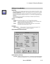
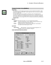
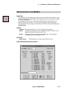
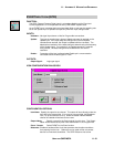
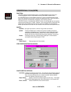
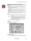
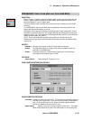
ICON CONFIGURATION DIALOG BOX:
CONFIGURATION OPTIONS:
Icon Name: Specify the name for the channel. This name will show directly under the
icon within the Program Net. If no name is User provided, the Backplane
Port (1 to 6) and Channel (A to D) where the actual Interface Module
channel is installed will be used for the name.
Output Name: Specify a name for the Output signal from this icon. This Output
Name will be referenced by other icons downstream in the Program Net.
Event / Counter Select COUNTER for the Counter function.