


11.. . APPENDIX A: MASTER ICON REFERENCE
USING THE OMP-MODL 11-59
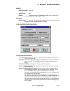
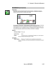
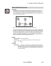
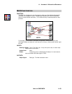
DUTY-CYCLE FUNCTION ICON
FUNCTION:
Calculates the amount of time per a User defined time period, that the input signal is True
(on) or False (off). Connected to the LOGIC output of an upstream icon (eg an Event
icon) the Duty Cycle icon will determine the accumulated ON or OFF (True/False) time
over a User defined time period and output that data value at the end of each period. It is
to be used with Logic input signals.
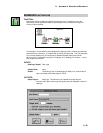
NOTE: For integration of DATA type signals refer to the Integral icon.
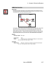
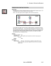
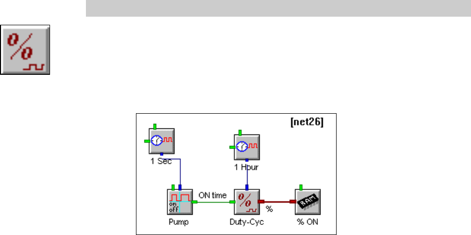
For example, to determine the ON time (duty cycle) per hour of a pump in a water supply
lift station. The pump power is sensed by an Event input channel which is sampling the
pump status (on/off) every second. The Event icon output is connected to the Duty cycle
icon input and an Update Clock is connected to the Duty cycle icon Update terminal. The
Duty cycle icon Update Clock is set for 1 Hour. The Duty cycle icon then samples its
input at a 1 second rate and calculates and outputs the ON (OFF) duty cycle of the input
signal upon receipt of an Update Clock pulse (ie every hour).
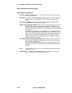
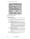
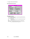
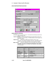
INPUTS:
Data/Logic Signal: Logic type (true/false).
Update Clock: Yes, specifies the time period over which the duty-cycle is
calculated
Enable: None
OUTPUTS:
Output Signal: Data type. The Duty-cycle icon updates its output after receiving
an Update Command from the connected Update Clock. The Output will
be in Percent (ie a number from 0 to 100) or a decimal format (ie a number
from 0.0 to 1.0) depending on the User specified Report format within the
Configuration Dialog.