


3... INTERFACE MODULES
USING THE OMP-MODL 3-1
3... INTERFACE MODULES
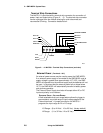
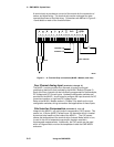
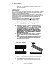
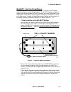
By adding Interface Modules (Figure 3... -1), the OMP-MODL System Base can be
expanded for additional I/O channels, modem, display, PCMCIA memory, and
battery operation. A full family of modules is available to meet most signal interface
and/or feature requirements.
This section covers the installation, wiring, hardware configuration, and application
considerations of the basic OMP-MODL family of Interface Modules. As additional
modules are added, the instruction sheets should be added to this section for
reference.
Programming and use of added Interface Module channels is done with the
HyperNet Program Net and is covered within Chapter 7 and the Master Icon
Reference in Appendix A.
HANDLING
As with all electronic systems, static electricity discharge can weaken or cause
permanent damage to circuitry. Protective circuitry is integral to the OMP-MODL
system including the Interface Modules, however when the Interface Modules are not
installed in the System Base, the protective circuitry is not effective. Therefore,
when handling Interface Modules, it is recommended that reasonable static control
procedures be followed.
♦ Before touching the Interface Module, discharge static electricity
built up in your body be touching a grounded point such as a
water faucet, cover plate screw on a receptacle, metal surface
of a grounded appliance or other earth ground.
♦ Do not wrap or store the Interface Module in static generating
materials such as untreated styrofoam packing `peanuts’ or
Inter-Module Connection bus
I/O Wiring Terminal
Strip
Side Retaining Screw holes
Figure 3... -1: Interface Module