4 – 3
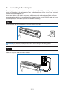
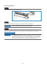
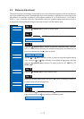
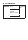
4.2 Reading the Auto Registration Marks
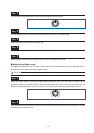
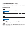
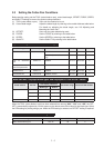
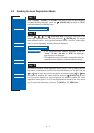
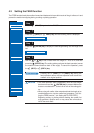
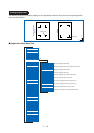
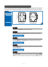
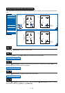
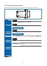
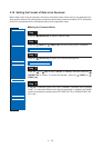
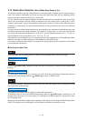
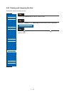
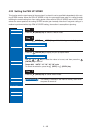
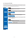
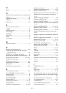
When “2 POINT,” “3 POINT,” or “4 POINT” has been set (see “4.6 Auto-Registra-
tion-Mark-Reading Settings”), press the (PAUSE) key to switch to PAUSE
mode and display the following menu.
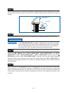
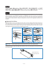
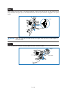
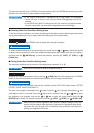
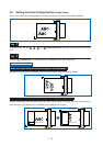
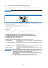
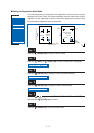
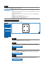
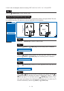
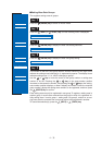
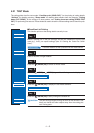
Use the , , , and (POSITION) keys to move the cutter pen to the
lower-right registration mark, and then press the (ENTER) key. The sensor
reads between points 1 and 2 (and also between points 1 and 3 for 3-point align-
ment or 4-point alignment), and the following is displayed.
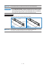
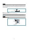
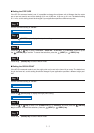
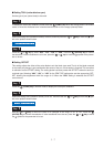
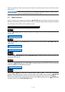
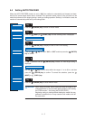
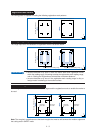
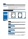
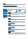
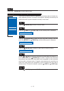
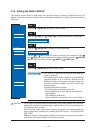
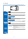
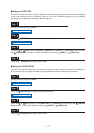
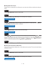
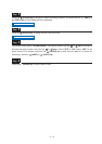
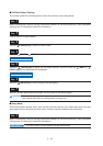
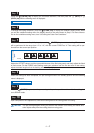
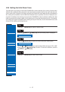
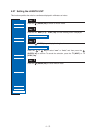
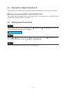
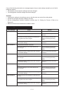
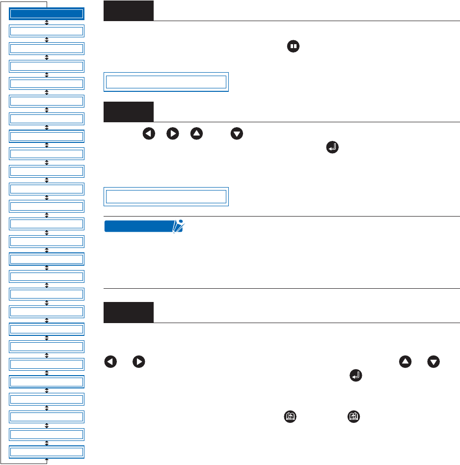
The distance between X-axis registration marks (points 1 and 2) read by the cut-
ting plotter is displayed on the left. Enter the actual distance on the right. Use the
or key to move the cursor to the digit to be entered, use the or key
to increase or decrease the values, and then press the (ENTER) key to con-
firm. For 3-point alignment or 4-point alignment, the distance between the Y-axis
registration marks (points 1 to 3) is also displayed and should be set in the same
way. To cancel the selection(s), press the (NEXT) or (PREV.) key.
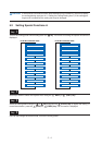
Step
1
Step
2
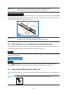
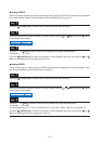
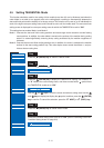
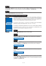
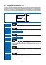
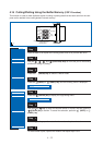
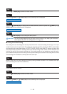
• If the registration-mark distance correction is set to
“5 mm,” “10 mm,” “50 mm,” or “STD.” the alignment
input screen is not displayed.
• The registration marks are read in accordance with the
registration-mark-detection movement distance setting.
Step
3
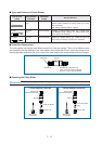
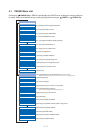
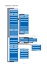
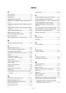
FEED
MOVE TO R. MARK
AUTO PRE FEED
TANGENTIAL
AUTO REG. MARK
CLEAR BUFFER
AXIS ALIGNMENT
DISTANCE ADJUST
PAGE LENGTH
PLOT AREA
EXPAND
ROTATE
MIRROR
COPY
SORT
RS-232C
COMMAND
BLADE WEAR SETUP
PEN UP/DOWN
TEST MODE
PEN UP SPEED
OFFSET FORCE
OFFSET ANGLE
STEP PASS
INIT. DOWN FORCE
LENGTH UNIT
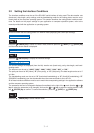
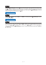
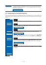
MOVE TO R. MARK
X00308.9 00308.9
CHECKPOINT