4 – 51
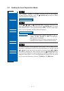
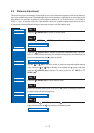
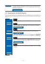
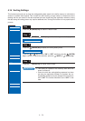
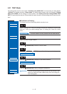
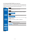
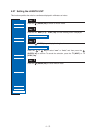
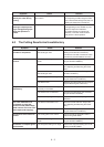
4.25 Setting the STEP PASS
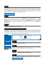
Reducing this setting increases image quality by enabling smooth cutter-blade tip control when arcs are
cut. The STEP PASS setting specified is used as the unit for blade tip control, with blade tip control omitted
for any data below the STEP PASS setting. If the STEP PASS setting is too high, the image cut may not be
faithfully reproduced. Normally, the STEP PASS setting should be set to “1.”
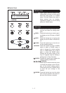
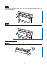
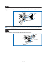
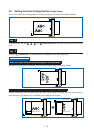
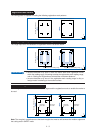
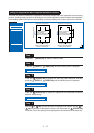
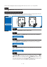
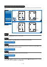
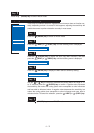
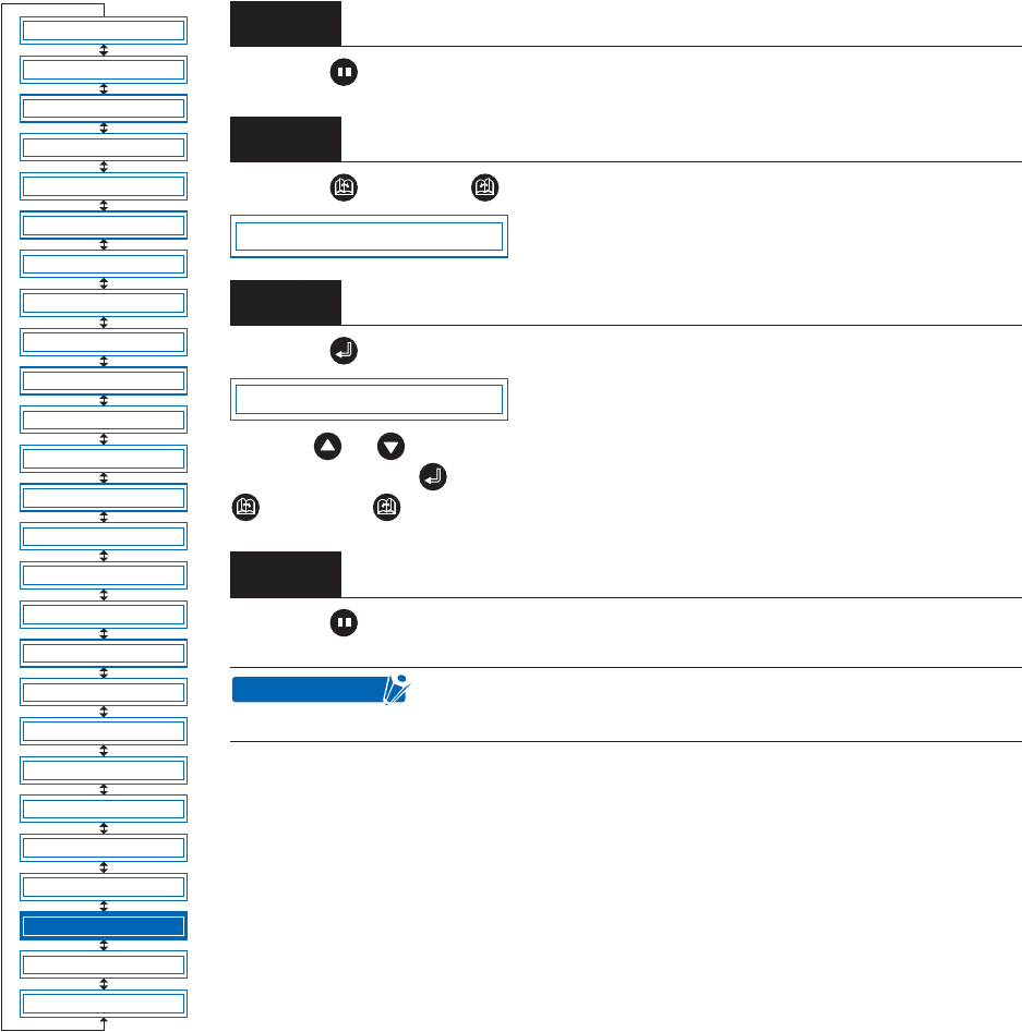
Press the (PAUSE) key to switch to PAUSE mode.
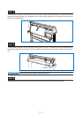
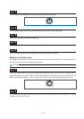
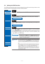
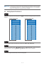
Press the (NEXT) or (PREV.) key until the following menu is displayed.
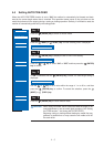
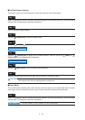
Press the (ENTER) key to display the step-pass setting menu.
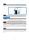
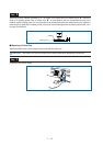
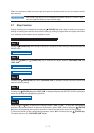
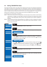
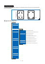
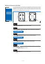
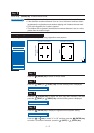
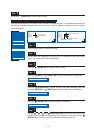
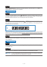
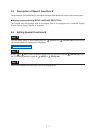
Use the or key to select the required value within the range of “0” to “20,”
and then press the (ENTER) key to confirm. To cancel the selection, press the
(NEXT) or (PREV.) key.
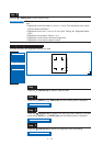
Press the (PAUSE) key to cancel PAUSE mode.
Step
1
Step
2
Step
3
Step
4
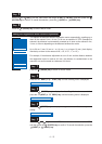
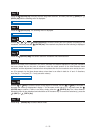
This setting is retained in the internal memory even when
the power is turned off.
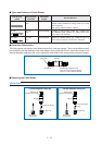
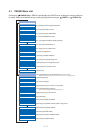
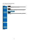
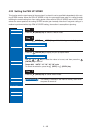
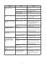
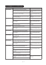
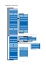
FEED
MOVE TO R. MARK
AUTO PRE FEED
TANGENTIAL
AUTO REG. MARK
CLEAR BUFFER
AXIS ALIGNMENT
DISTANCE ADJUST
PAGE LENGTH
PLOT AREA
EXPAND
ROTATE
MIRROR
COPY
SORT
RS-232C
COMMAND
BLADE WEAR SETUP
PEN UP/DOWN
TEST MODE
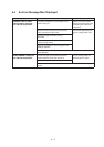
PEN UP SPEED
OFFSET FORCE
OFFSET ANGLE
STEP PASS
INIT. DOWN FORCE
LENGTH UNIT
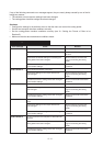
STEP PASS
STEP PASS 1
CHECKPOINT