4 – 39
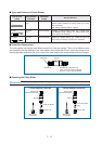
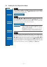
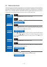
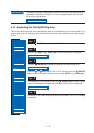
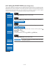
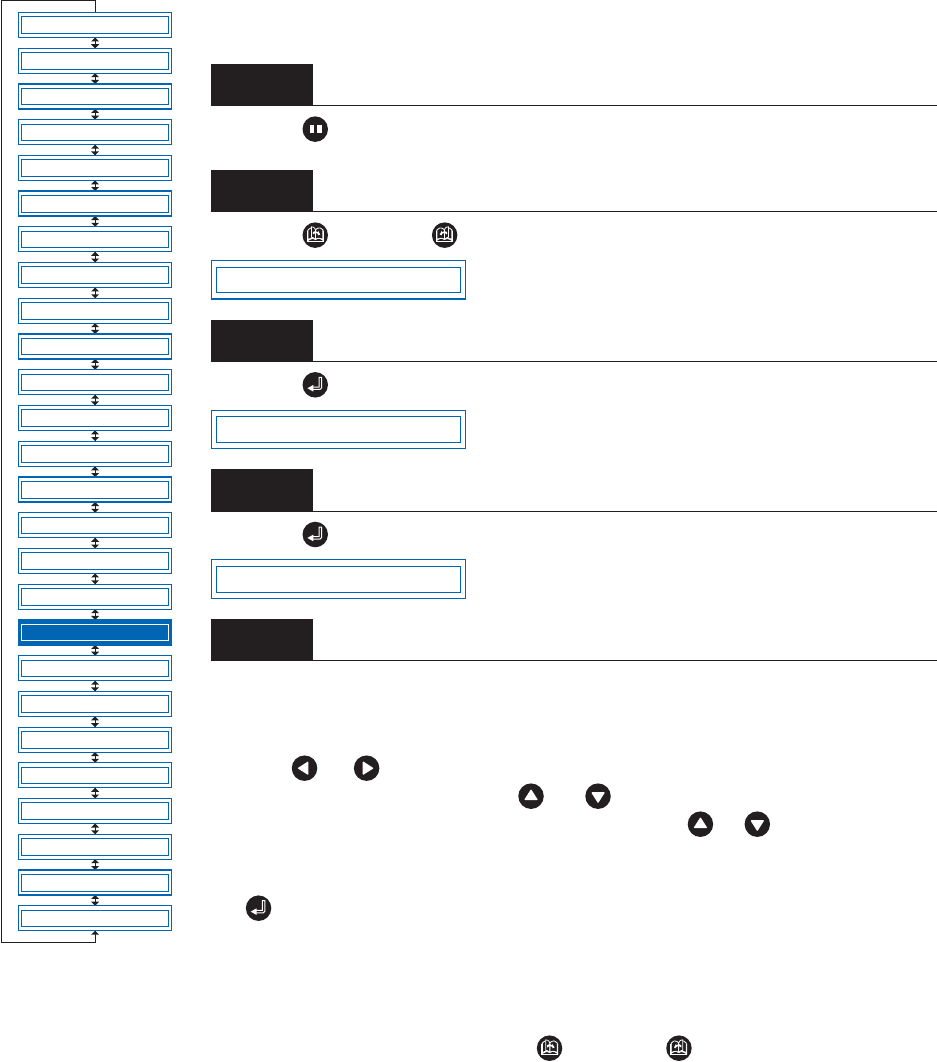
■Setting Wear-Rate Groups
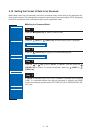
This registers setting areas in groups.
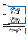
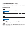
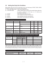
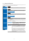
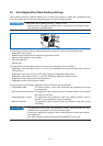
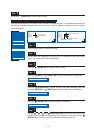
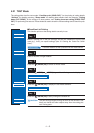
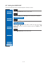
Press the (PAUSE) key to switch to PAUSE mode.
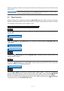
Press the (NEXT) or (PREV.) key until the following menu is displayed.
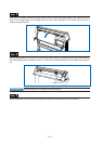
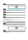
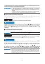
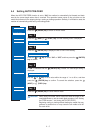
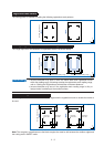
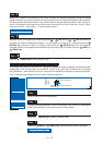
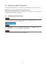
Press the (ENTER) key to display the wear-rate setting submenu.
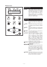
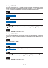
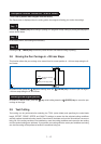
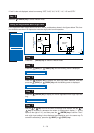
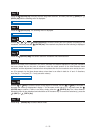
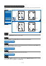
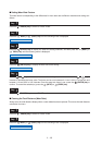
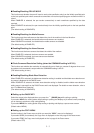
Press the (ENTER) key to display the wear-rate group setting.
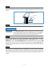
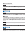
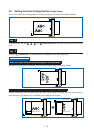
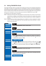
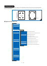
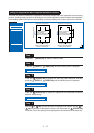
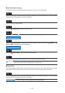
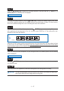
The number on the left is the group number, and the numbers to the right of this
indicate the setting areas belonging to it, separated by spaces. The display above
indicates setting areas 1, 2, 4, and 5, belonging to group 1.
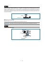
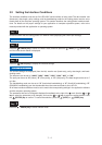
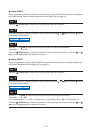
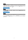
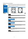
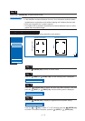
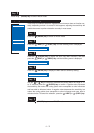
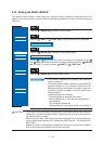
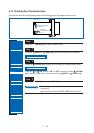
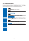
Use the or key to move the cursor to the group number or setting-area
number to be set. Pressing the or key at the group-number position
increases or decreases the number, and pressing the or key at the setting-
area number position displays or doesn’t display the number. Select the required
group number, display the setting-area numbers to be registered, and then press
the (ENTER) key to confirm.
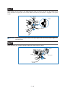
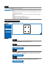
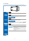
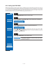
Each setting area can only be registered in one group. To register a setting area in
another group, it must first be removed from the group in which it is registered. Ini-
tially, setting area 1 is set to group 1, setting area 2 to group 2, and so on, so set-
ting areas must be removed from one group before being registered in another.
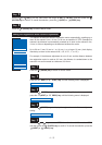
To cancel the selection(s), press the (NEXT) or (PREV.) key.
Step
1
Step
2
Step
3
Step
4
Step
5
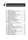
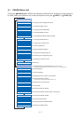
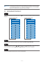
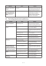
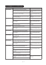
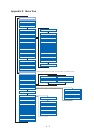
FEED
MOVE TO R. MARK
AUTO PRE FEED
TANGENTIAL
AUTO REG. MARK
CLEAR BUFFER
AXIS ALIGNMENT
DISTANCE ADJUST
PAGE LENGTH
PLOT AREA
EXPAND
ROTATE
MIRROR
COPY
SORT
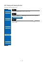
RS-232C
COMMAND
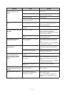
BLADE WEAR SETUP
PEN UP/DOWN
TEST MODE
PEN UP SPEED
OFFSET FORCE
OFFSET ANGLE
STEP PASS
INIT. DOWN FORCE
LENGTH UNIT
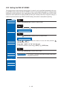
BLADE WEAR SETUP
SET BLADE GROUP
GROUP 1 12 45