Page 4 - 10
Installation F - 160 CE Operation and Maintenance Manual
© GBC Films Group April 2000
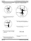
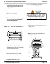
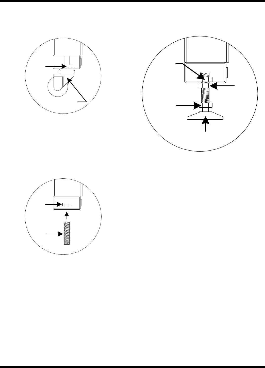
Figure 4.7.1 Leveling pad installed
Leveling pad
Jam nut
Nut
Nut
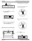
i) Tighten the jam nut against the leveling pad.
Refer to Figure 4.7.1 Leveling pad installed.
j) Perform steps e through “ i ” for the rear control
side castor and leveling pad.
Drive side
a) Perform steps “ a ” through “ j ” from the
Control side.
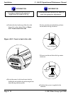
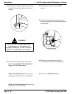
e) Remove the front control side castor by turning
the nut securing the castor in the leg.
Castor
Nut
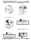
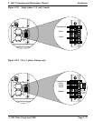
f) Slide one of the leveling bolts where the castor
was removed and along with a 3/4-10 nut
inside the leg.
Bolt
Nut
g) Place two more 3/4-10 nuts on the leveling bolt
under the leg. Refer to Figure 4.7.1 Leveling
pad installed.
h) Attach the leveling pad to the bottom of the
leveling bolt and secure with wrenches. Refer to
Figure 4.7.1 Leveling pad installed.


