


Page 4 - 16
Installation F - 160 CE Operation and Maintenance Manual
© GBC Films Group April 2000
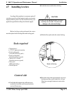
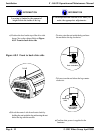
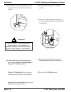
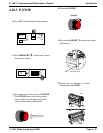
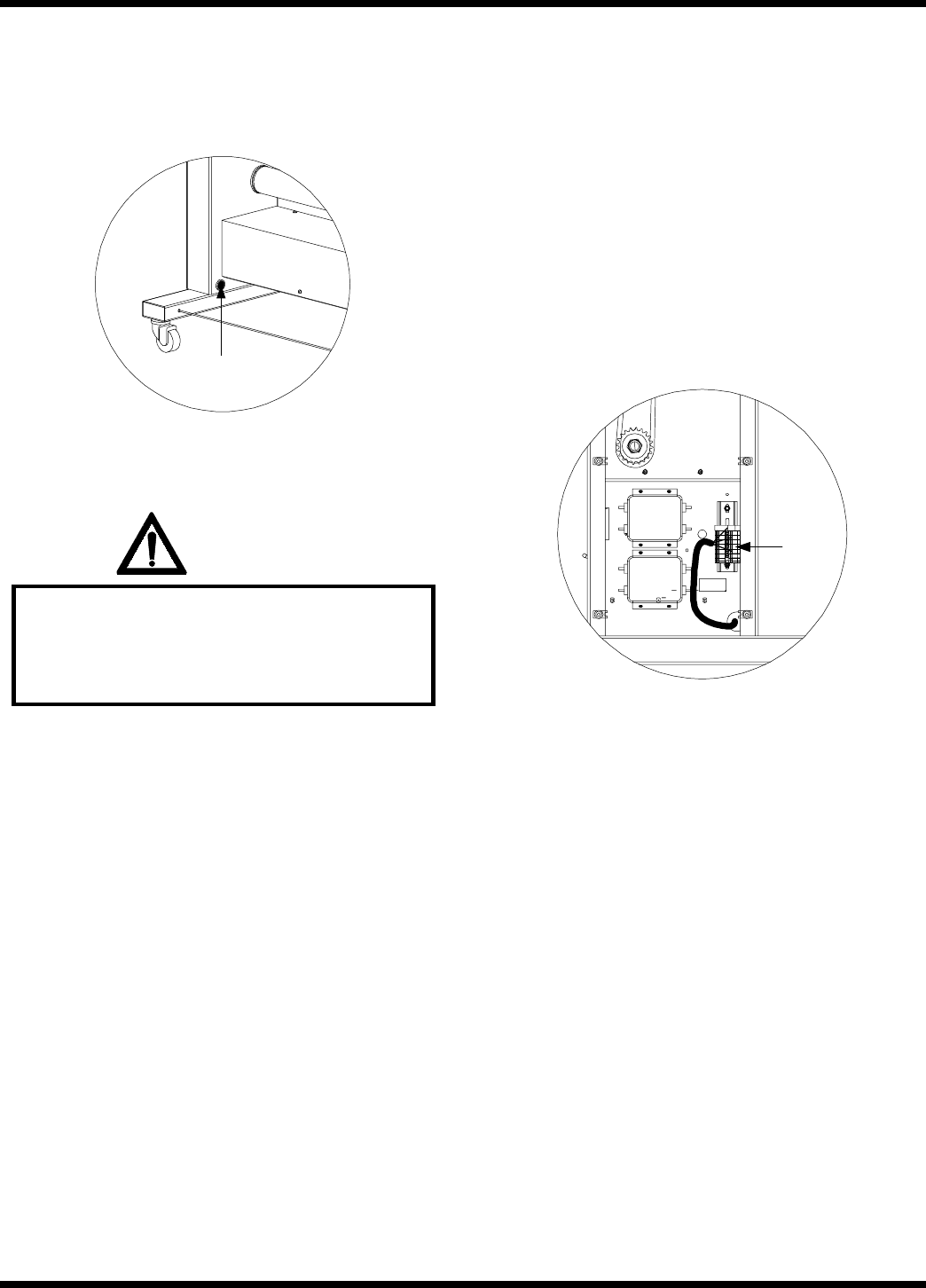
c) Feed the power cable through the power cable
strain relief located at the bottom of the drive
side leg.
Strain relief
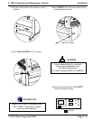
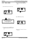
WARNING
Follow the correct wiring diagram when
supplying power to the laminator. If
improperly connected, you can be seriously
injured or cause damage to the laminator.
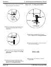
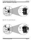
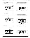
d) Connect the power cord to the line terminal
block. Refer to Figure 4.9.1 Single phase or
Figure 4.9.2 Wye three phase.
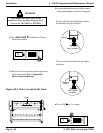
Figure 4.9.1 Single phase illustrates proper
single phase wiring for the U.S. and Canada.
Figure 4.9.2 Wye three phaseillustrates proper
Wye 3 phase wiring for Europe.
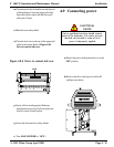
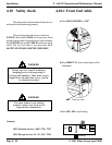
e) Turn the junction box power to the ON
position.
f) Verify line voltage with regards to the type of
power being supplied to the laminator at the line
terminal block.
Line
terminal
block
g) Once the power cord has been properly
connected, replace the drive side leg cover.
h) Proceed with 4.10 Safety check.