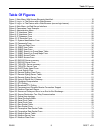
Table Of Figures
Figure 48: WIN and TIN Form.................................................................................................................77
Figure 49: MicroLok Form.......................................................................................................................79
Figure 50: DNP Form..............................................................................................................................80
Figure 51: Mirrored Bits Table ................................................................................................................81
Figure 52: Mirrored Bits Form.................................................................................................................82
Figure 53: Device Address Table............................................................................................................83
Figure 54: Device Address Form ............................................................................................................84
Figure 55: Dynamic Device Address Table.............................................................................................85
Figure 56: Dynamic Device Address Form .............................................................................................85
Figure 57: Links Statistics Table.............................................................................................................86
Figure 58: Links Statistics Form..............................................................................................................87
Figure 59: Connection Statistics Table ...................................................................................................88
Figure 60: Serial Port Statistics Table.....................................................................................................89
Figure 61: Clear Serial Port Statistics Form............................................................................................90
Figure 62: Reset Serial Port(s) Form......................................................................................................90
Figure 63: Controller Protection Through LFI .........................................................................................93
Figure 64: Ethernet Ports Menu..............................................................................................................95
Figure 65: Port Parameters Table...........................................................................................................96
Figure 66: Port Parameters Form ...........................................................................................................96
Figure 67: Port Rate Limiting Table ........................................................................................................99
Figure 68: Port Rate Limiting Form.........................................................................................................99
Figure 69: Port Mirroring Form..............................................................................................................101
Figure 70: Link Detection Form.............................................................................................................102
Figure 71: Accessing PoE Parameters.................................................................................................103
Figure 72: PoE Parameters Table ........................................................................................................103
Figure 73: PoE Parameters Form.........................................................................................................104
Figure 74: Accessing EoVDSL Parameters..........................................................................................106
Figure 75: EoVDSL Parameters Table .................................................................................................106
Figure 76: EoVDSL Parameters Form..................................................................................................107
Figure 77: Port Status Table.................................................................................................................108
Figure 78: Ethernet Port Statistics Menu ..............................................................................................111
Figure 79: Ethernet Statistics Table......................................................................................................112
Figure 80: Ethernet Port Statistics Table ..............................................................................................114
Figure 81: Ethernet Port Statistics Form...............................................................................................115
Figure 82: Clear Ethernet Port Statistics Form .....................................................................................119
Figure 83: RMON History Controls Table .............................................................................................120
Figure 84: RMON History Controls Form..............................................................................................121
Figure 85: RMON History Samples Table.............................................................................................122
Figure 86: RMON History Samples Form .............................................................................................123
Figure 87: The Alarm Process ..............................................................................................................126
Figure 88: RMON Alarms Table............................................................................................................126
Figure 89: RMON Alarms Form ............................................................................................................127
Figure 90: RMON Events Table............................................................................................................129
Figure 91: RMON Events Form ............................................................................................................130
Figure 92: RMON Event Log Table.......................................................................................................131
Figure 93: RMON Event Log Form .......................................................................................................132
Figure 94: Bridge and Port States ........................................................................................................134
Figure 95: Bridge and Port Roles .........................................................................................................135
Figure 96: Example of a Structured Wiring Configuration.....................................................................143
Figure 97: Example of a Ring Backbone Configuration........................................................................144
Figure 98: Port Redundancy.................................................................................................................145


