


Spanning Tree
RS400 133 ROS™ v3.5
5 Spanning Tree
The RuggedSwitch™ family of Ethernet switches provide the latest in IEEE standard Spanning
Tree functionality, including:
• Industry standard support of Rapid Spanning Tree (802.1D-2004), which features a
compatibility mode with legacy STP (802.1D-1998)
• Industry standard support of Multiple Spanning Trees (802.1s and 802.1Q-2003), which is
interoperable with both RSTP and legacy STP.
• RuggedCom RSTP feature enhancements (eRSTP™)
• Superior performance - RSTP will recognize a link failure and put an alternate port into
forwarding within milliseconds.
• RSTP may be enabled on a per-port basis.
• Ports may be configured as edge ports, which allow rapid transitioning to the forwarding
state for non-STP hosts.
• Path costs may be hard-configured or determined by port speed negotiation, in either the
STP or RSTP style.
• Full bridge
1
and port status provide a rich set of tools for performance monitoring and
debugging.
• SNMP manageable including newRoot and topologyChange traps
5.1 RSTP Operation
The 802.1D Spanning Tree Protocol was developed to allow the construction of robust networks
that incorporate redundancy while pruning the active topology of the network to prevent loops.
While STP is effective, it requires that frame transfer must halt after a link outage until all
bridges in the network are sure to be aware of the new topology. Using the 802.1D
recommended values, this period lasts 30 seconds.
The Rapid Spanning Tree Protocol (IEEE 802.1w) was a further evolution of the 802.1D
Spanning Tree Protocol. It replaced the settling period with an active handshake between
bridges that guarantees the rapid propagation of topology information through the network.
RSTP also offers a number of other significant innovations, including:
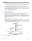
• Topology changes in RSTP can originate from and be acted upon by any designated
bridges, leading to more rapid propagation of address information, unlike topology changes
in STP, which must be passed to the root bridge before they can be propagated to the
network.
• RSTP explicitly recognizes two blocking roles, alternate and backup port roles, including
them in computations of when to learn and forward while STP recognizes one state,
blocking, for ports that should not forward.
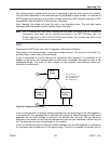
• RSTP bridges generate their own configuration messages, even if they fail to receive any
from the root bridge. This leads to quicker failure detection. STP, by contrast, must relay
configuration messages received on the root port out its designated ports. If an STP bridge
fails to receive a message from its neighbor it cannot be sure where along the path to the
root a failure occurred.
1
Historically, a device implementing STP on its ports has been referred to as a bridge. RuggedCom uses the term
bridge and switch synonymously.