


Appendix E – ModBus Management Support and Memory Map
ROS™ v3.5 272 RS400
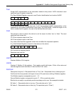
Read Data from device using PortCmd:
E.g. A Modbus Request to read multiple registers from location – 0x03FE
0x04 0x03 0xFE 0x00 0x02
Response would depend on the device as on how many ports are available on the device
E.g. If Max number of ports on RuggedCom device to which you are talking to is 20
Response may look like:
0x04 0x04 0xF2 0x76 0x00 0x05
In the above response Byte 3 and 4 refer to Register 1 i.e register at location 0X03FE indicating
port status of ports 1 –16 and Byte 5 and 6 representing register 2 at location 0x03FF would
refer to port status from 17-32, though in this case since device has only 20 ports so byte 6
would contain the status for ports 17-20 starting from right to left. Rest of the bits in register 2
corresponding to non-existing ports would be zero.
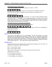
Performing write actions on the device using PortCmd:
Write multiple register request to clear Ethernet port statistics
0x10 0x00 0x83 0x00 0x01 2 0x55 0x76 0x00 0x50
Bit value 1 implies clear Ethernet statistics on a corresponding port. Bit value 0 corresponding to
a port means do nothing.
Response may look like:
0x10 0x00 0x81 0x00 0x02
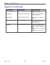
Alarm
This format is also another form of text description. This text corresponds to the alarm
description from the table holding all the alarms. Similar to the ‘Text ’ format this format would
also have ASCII representation of alarms. Please note that alarms are stacked in RuggedCom
device in the sequence of their occurrences. So first alarm on the stack would be Alarm1, next
latched alarm in the device is Alarm 2 and so on. User has capability of seeing first 8 alarms
from the stack if they exist. Zero value is sent if an alarm does not exist.
PSStatusCmd
Descriptive bit layout for providing the status of available power supplies in the unit. Bits 0-4 of
lower byte of the register are used for this purpose.
Bits 0-1: Power Supply 1 Status
Bits 2-3: Power supply 2 Status
Rest of the bits in the register do not provide any system status info at this time
Interpretation of the values:
01: Power Supply not present (1)
10: Power Supply is functional (2)
11: Power Supply is not functional (3)