


Spanning Tree
ROS™ v3.5 142 RS400
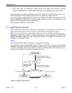
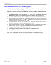
5.2.4 Implementing MSTP on a Bridged Network
It is recommended that the configuration of MSTP on a network proceed in the sequence
outlined below. Naturally, it is also recommended that network analysis and planning inform the
steps of configuring the VLAN and MSTP parameters in particular.
Begin with a set of MSTP-capable Ethernet bridges, and MSTP disabled. For each bridge in the
network:
1. Configure and enable RSTP (see sections 5.4.1 and 5.4.2). Note that the Max Hops
parameter in the Bridge RSTP Parameters menu is the maximum hop count for MSTP.
2. Create the VLANs that will be mapped to MSTIs (see the sections on VLAN Configuration).
3. Map VLANs to MSTIs (via the VLAN Configuration menus). Note that MSTP need not be
enabled in order to map a VLAN to an MSTI. Note also that this mapping must be identical
for each bridge that is to belong to the MST region.
4. Configure a Region Identifier and Revision Level. Note that these two items must be
identical for each bridge in the MST region (see section 5.4.3).
5. Verify that the Digest field in the MST Region Identifier menu is identical for each bridge in
the MST region. If it is not, then the set of mappings from VLANs to MSTIs differs.
6. Configure Bridge Priority per MSTI (see section 5.4.4).
7. Configure Port Cost and Priority per port and per MSTI (see section 5.4.5).
8. Enable MSTP (see section 5.4.1).
Note Static VLANs must be used in an MSTP configuration. GVRP is not supported in this case.