


Table Of Figures
RS400 9 ROS™ v3.5
Table Of Figures
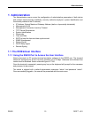
Figure 1: Main Menu With Screen Elements Identified...........................................................................16
Figure 2: Log in to The Device with a Web Browser..............................................................................19
Figure 3: Log in to The Device with a Web Browser (secure login banner)...........................................20
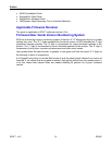
Figure 4: Main Menu via Web Server Interface ......................................................................................21
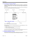
Figure 5: Parameters Form Example......................................................................................................22
Figure 6: Administration Menu................................................................................................................24
Figure 7: IP Interfaces Table ..................................................................................................................25
Figure 8: IP Interfaces Form ...................................................................................................................26
Figure 9: IP Gateways Form...................................................................................................................28
Figure 10: IP Services Form ...................................................................................................................29
Figure 11: System Identification Form ....................................................................................................31
Figure 12: Passwords Form....................................................................................................................32
Figure 13: Time and Date Form..............................................................................................................34
Figure 14: SNMP User Table..................................................................................................................36
Figure 15: SNMP User Form ..................................................................................................................37
Figure 16: SNMP Security to Group Maps Table....................................................................................38
Figure 17: SNMP Security to Group Maps Form ....................................................................................38
Figure 18: SNMP Access Table..............................................................................................................39
Figure 19: SNMP Access Form ..............................................................................................................40
Figure 20: RADIUS Server summary......................................................................................................44
Figure 21: RADIUS Server Form ............................................................................................................44
Figure 22: TACACS+ Server summary...................................................................................................46
Figure 23: TACACS+ Server Form .........................................................................................................47
Figure 24: DHCP Relay Agent Form.......................................................................................................48
Figure 25: Local Syslog Form.................................................................................................................49
Figure 26: Remote Syslog Client Form...................................................................................................50
Figure 27: Remote Syslog Server Table.................................................................................................50
Figure 28: Remote Syslog Server Form .................................................................................................51
Figure 29: Using A Router As A Gateway...............................................................................................52
Figure 30: Character Encapsulation .......................................................................................................55
Figure 31: RTU Polling ...........................................................................................................................55
Figure 32: Broadcast RTU Polling ..........................................................................................................56
Figure 33: Permanent and Dynamic Master Connection Support ..........................................................57
Figure 34: Modbus Client and Server .....................................................................................................59
Figure 35: Sources of Delay and Error in an End-to-End Exchange ......................................................60
Figure 36: Source/Destination Two Way Communication ......................................................................62
Figure 37: Optical loop topology .............................................................................................................66
Figure 38: Serial Protocols Menu............................................................................................................67
Figure 39: Serial Ports Table ..................................................................................................................68
Figure 40: Serial Ports Form...................................................................................................................68
Figure 41: Raw Socket Table .................................................................................................................70
Figure 42: Raw Socket Form ..................................................................................................................71
Figure 43: Preemptive Raw Socket Table ..............................................................................................73
Figure 44: Preemptive Raw Socket Form...............................................................................................73
Figure 45: Modbus Server Table ............................................................................................................75
Figure 46: Modbus Server Form.............................................................................................................75
Figure 47: Modbus Client Form ..............................................................................................................76