


1 Quick Reference
10 Series N6700 User’s Guide
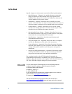
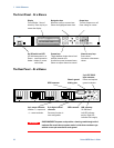
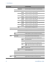
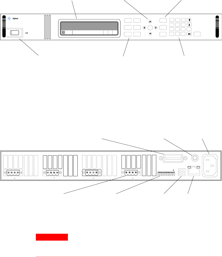
The Front Panel - At a Glance
Display
Turns off after 1 hour of
inactivity. Press any key to
restore the display.
Navigation keys
Move the cursor to a menu item.
Select the highlighted menu item.
Output keys
Turn the outputs on or off.
Enter voltage or current.
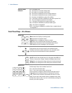
N6700A Modular Power System
20.007V 4.004A
CV Set: 20.000V 5.500A
o -
Menu
3
E
+/-
Back
.
2
0
1
456
987
Sel
Meter
Channel
Help
On/Off
Voltage
Current
1
Error
Enter
On/Off switch and LED
LED indicates power is on.
Green = normal operation.
Amber = display is screen-
saver mode.
System keys
Toggle between single-channel and
multiple-channel view.
Access front panel command menu.
Select an output channel to control.
Numeric entry keys
Enter values.
Increment or decrement
values.
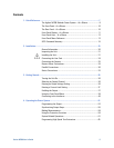
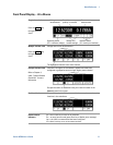
The Rear Panel – At a Glance
GPIB connector
Chassis ground
binding post
3-pin IEC 320 AC
input connector
Power cord requires
ground conductor.
+s + -s
+s + -s
+s + -s +s + -s
1 2 3 4 5 6 7
4-pin output connector.
Includes +/−output and
+/− sense terminals.
8-pin digital control
connector
Connector function is
user-configurable.
USB connector LAN connector
10/100 Base-T
Left LED indicates
activity. Right LED
indicates link integrity.
WARNING
SHOCK HAZARD The power cord provides a chassis ground through a third
conductor. Be certain that your power outlet is of the three-conductor type
with the correct pin connected to earth ground.