


Output On/Off Synchronization Appendix D
Series N6700 User’s Guide 103
Synchronizing Multiple Mainframes
The output turn-on synchronization function can be used across
multiple mainframes that have coupled output channels. Each
mainframe that will be synchronized must have at least one coupled
channel. Note that cross-frame synchronization must be enabled for
any mainframe that contains synchronized output channels.
Procedure
1. Configure the output channels on each mainframe as described
in steps 1 through 3 of the previous procedure.
2. This step is required if you have power modules with different
minimum delay offsets. Specify a common delay offset for all of
the synchronized output channels. This value must be the largest
delay offset of all synchronized output channels regardless of the
mainframe in which they are installed. This same value must be
specified as the common delay offset for each mainframe.
Front Panel: SCPI Command:
In the front panel menu of each
mainframe, select
Output\Couple.
In the Delay offset field, enter the
delay offset value of the slowest
power module of all the mainframes
in milliseconds; then press Select.
The Max delay offset for this frame
field displays the delay offset of the
slowest power module in this frame.
To specify the common delay offset
for each mainframe in seconds:
OUTP:COUP:DOFF .051
To return the delay offset of the
slowest power module in each
mainframe (the maximum delay
offset) in seconds:
OUTP:COUP:MAX:DOFF?
3. Connect and configure the digital connector pins of the
synchronized mainframes as described in the following section.
Digital Connections and Configuration
NOTE
Only pins 4 through 7 can be configured as synchronization pins. You cannot
configure more than one ON couple and one OFF couple pin per mainframe.
The polarity of the pins is not programmable.
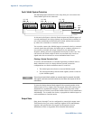
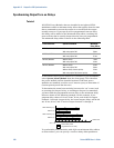
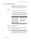
The digital connector pins of the synchronized mainframes that
contain coupled channels must be connected together as shown in
the following figure. In this example, pin 6 will be configured as the
output On control. Pin 7 will be configured as the output Off control.
The ground or Common pins also need to be connected together.