


Using the Digital Port Appendix B
Series N6700 User’s Guide 93
Fault Output
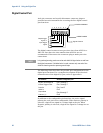
Pins 1 and 2 can be configured as a fault-output pair. The polarity of
pin 1 can also be configured. Pin 1 is the Fault output; pin 2 is the
common for pin 1. Note that pin 2 must also be connected to pin 8.
The Fault Output function enables a fault condition on any channel
to generate a fault signal on the Digital Control port. The following
conditions will generate a fault event: over-voltage, over-current,
over-temperature, inhibit signal, power-fail condition, or on some
models, a power-limit condition.
Both pins 1 and 2 are dedicated to this function. This provides for an
optically-isolated output. Pin 2’s function is ignored. Note that the
Fault output signal remains latched until the fault condition is
cleared. You must also clear the protection circuit.
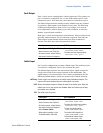
Front Panel: SCPI Command:
Select System\IO\DigPort\Pin1.
Select Function, then Fault Out.
Go back one level, select Polarity,
then either Positive or Negative.
To configure the Fault function:
DIG:PIN1:FUNC FAUL
To select the fault output polarity:
DIG:PIN1:POL <pol>
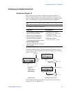
Inhibit Input
Pin 3 can be configured as a remote inhibit input. The polarity of pin
3 can also be configured. Pin 8 is the common for pin 3.
The Inhibit Input function lets an external input signal control the
output state of all of the output channels in the mainframe. The
signal latency is 5 microseconds. Pin 3 can be programmed for the
following Inhibit modes, which are stored in non-volatile memory:
LATChing Causes a logic-true transition on the Inhibit input to disable all outputs. The
outputs will remain disabled after the inhibit signal is received.
LIVE Allows the enabled outputs to follow the state of the Inhibit input. When the
Inhibit input is true, the outputs are disabled. When the Inhibit input is false,
the outputs are re-enabled.
OFF The Inhibit input is ignored.
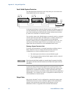
Front Panel: SCPI Command:
Select System\IO\DigPort\Pin3.
Select Function, then Inhibit In.
Go back one level, select Polarity,
then either Positive or Negative.
Select Protect\Inhibit.
Select either Latching or Live.
To disable Inhibit, select Off
To configure the Inhibit function:
DIG:PIN3:FUNC INH
To select the inhibit input polarity:
DIG:PIN3:POL <pol>
To latch the Inhibit signal:
OUTP:INH:MODE LATC
To set the Inhibit signal live:
OUTP:INH:MODE LIVE
To disable the Inhibit signal:
OUTP:INH:MODE OFF