


Using the Digital Port Appendix B
Series N6700 User’s Guide 91
Configuring the Digital Control Port
Bi-directional Digital I/O
Each of the seven pins can be configured as general purpose bi-
directional digital inputs and outputs. The polarity of the pins can
also be configured. Pin 8 is the signal common for the digital I/O pins.
Data is programmed according to the following bit assignments:
Pin 1 2 3 4 5 6 7
Bit 0 1 2 3 4 5 6
To configure the pins for digital I/O:
Front Panel: SCPI Command:
Select System\IO\DigPort\Pin<n>,
where <n> is the pin number.
Select Function, then Digital I/O.
Go back one level, select Polarity,
then either Positive or Negative.
To send digital data to the pins, select
System\IO\DigPort\Data.
Select Data Out and enter the data as
a binary number.
To configure the pin function:
DIG:PIN<1-7>:FUNC DIO
To configure pin polarity:
DIG:PIN<1-7>:POL <pol>
To send data to the pins:
DIG:OUTP:DATA <data>
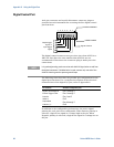
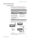
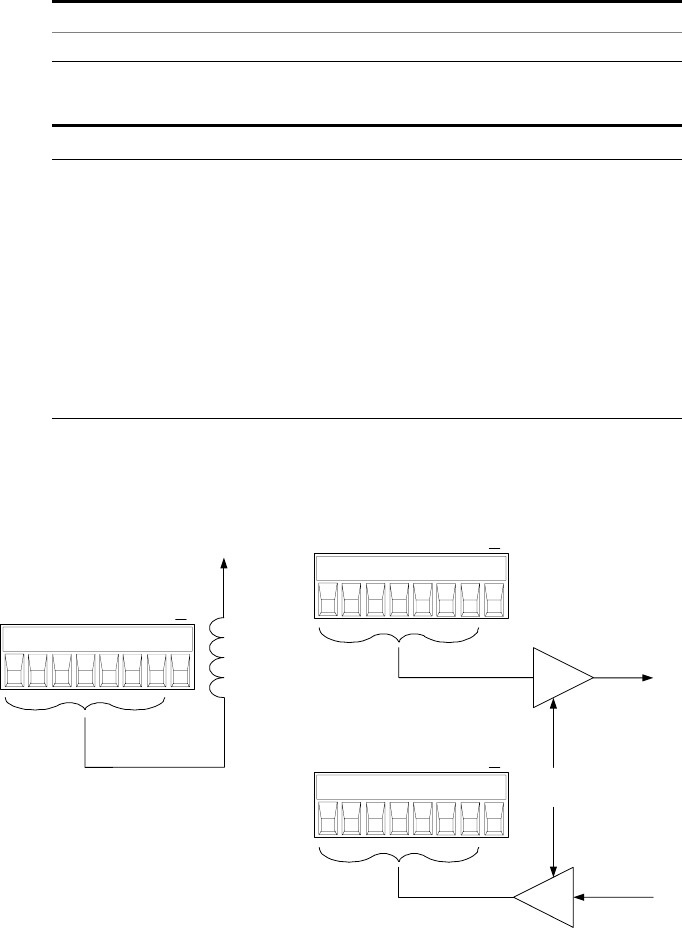
The digital I/O pin can be used to control both relay circuits as well
as digital interface circuits. The following figure illustrates typical
relay circuits as well as digital interface circuit connections using the
digital I/O functions.
For a complete description of the electrical characteristics of the
digital I/O port, see Appendix A.
B) Digital Interface CircuitsA) Relay Circuits
TTL, AS, CMOS, HC
Relay driver
Ports 0, 1, 2.
(contains internal
clamp diodes for
inductive flyback)
Coil
Current
0.1 A
Max.
16.5 V Max.
Digital Output
Ports 0, 1, 2
Digital Input
Ports 0, 1, 2
1 2 3 4 5 6 7
I
1 2 3 4 5 6 7
I
1 2 3 4 5 6 7
I