


2 Installation
32 Series N6700 User’s Guide
On mainframes with earlier version firmware, first program both
outputs to the desired output voltage. Then program the current limit
point of each output. The current limit of the paralleled outputs will
be the sum of both individual current limit points.
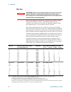
Effect on Specifications
Specifications for outputs operating in parallel can be obtained from
the specifications for single outputs. Most specifications are
expressed as a constant or as a percentage (or ppm) plus a constant.
For parallel operation, the percentage portion remains unchanged
while constant portions or any constants are changed as indicated
below. For current readback accuracy and temperature coefficient of
current readback, use the minus current specifications:
Current All parallel specifications referring to current are twice the single output
specification except for programming resolution, which is the same for both
single output and parallel output operation.
Voltage All parallel specifications referring to voltage are the same as for a single
output except for CV load effect, CV load cross regulation, CV source effect,
and CV short term drift. These are all twice the voltage programming accuracy
(including the percentage portion) at all operating points.
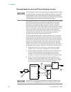
Load Transient
Recovery Time
Load transient specifications are typically twice the single output.
Series Connections
WARNING
SHOCK HAZARD Floating voltages must not exceed 240 VDC. No output
terminal may be more than 240 VDC from chassis ground.
CAUTION
Only connect outputs that have identical voltage and current ratings in series.
To prevent currents from damaging the power system when the load is
connected, always turn series-connected outputs on and off together.
Do not leave one output on while the other is off.
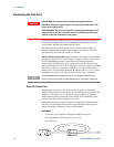
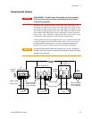
Connecting outputs in series provides a greater voltage capability
than can be obtained from a single output. Because the current is the
same through each element in a series circuit, outputs connected in
series must have equivalent current ratings.
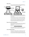
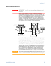
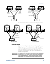
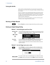
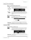
The following figures show how to connect two outputs in series to a
single load. If voltage drop in the load leads is a concern, connect the
sense leads of output 1 and output 2 for remote sensing as shown in
the figure on the right. Note that the +sense lead of output 2 must
remain connected to the -sense terminal of output 1.