


Appendix B Using the Digital Port
94 Series N6700 User’s Guide
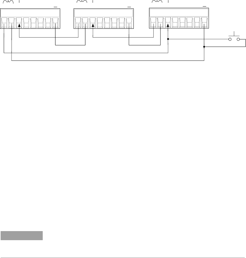
Fault/Inhibit System Protection
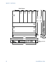
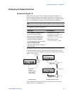
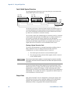
The following figure illustrates some ways that you can connect the
Fault/Inhibit pins of the connector.
As shown in the figure, when the Fault outputs and Inhibit inputs of
several mainframes are daisy-chained, an internal fault condition in
one of the mainframes will disable all of them without intervention
by either the controller or external circuitry.
You can also connect the Inhibit input to a manual switch or external
control signal that will short the Inhibit pin to common whenever it
is necessary to disable all output channels in the mainframe.
Negative polarity must be programmed for all pins in this case. You
can also use the Fault output to drive an external relay circuit or
signal other devices whenever a user-definable fault occurs.
Clearing a System Protection Fault
To restore all instruments to a normal operating condition when a
fault condition occurs in a daisy-chained system protection
configuration, two fault conditions must be removed:
1. The initial protection fault or external Inhibit signal.
2. The subsequent daisy-chained fault signal (which is sourced
by the Inhibit signal).
NOTE
Even when the initial fault condition or external signal is removed, the Inhibit
fault signal is still active and will continue to shut down the outputs of all the
mainframes.
To clear the daisy-chained fault signal if the operating mode of the
Inhibit input is Live, simply clear the output protection on any
ONE
mainframe as explained in chapter 4. If the operating mode of the
Inhibit input is Latched, turn off the Inhibit input on
ALL mainframes
individually. To re-enable the chain, re-program the Inhibit input on
each mainframe to Latched mode.
Output State
Only pins 4 through 7 can be configured to control the output state.
This function lets you connect multiple Agilent N6700 mainframes
together and synchronize the output on/off sequence across
mainframes. Refer to Appendix D for detailed information.
Panic
switch
INH
Common
INH
Input
FLT
INH
1 2 3 4 5 6 7
I
1 2 3 4 5 6 7
I
1 2 3 4 5 6 7
I
FLT
INH
FLT
INH
+ - + -
+ -