


2 Installation
28 Series N6700 User’s Guide
Protecting Sensitive Loads from AC Power Switching Transients
NOTE
This only applies if you are connecting loads that are highly sensitive to voltage
or current transients to the output of the modular power system. If your load is
connected directly to the output of the power system and is not connected to
chassis ground in any way, you do not need to worry about AC power switching
transients appearing at the output of the modular power system.
Operating the AC line switch can inject common mode current spikes
into the DC output leads, resulting in voltage spikes, which may
damage sensitive loads. Note that any electronic device meeting
international standards for EMI compliance is likely to generate
similar current spikes. This situation arises from the presence of EMI
filters at both the AC input and the DC output of the modular power
system. These filters typically include common mode capacitors
connected to the power system chassis. Since the AC input has an
earth ground, any load that is also earth-grounded provides a
possible return path for common mode currents.
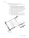
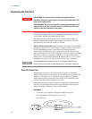
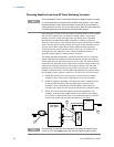
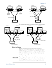
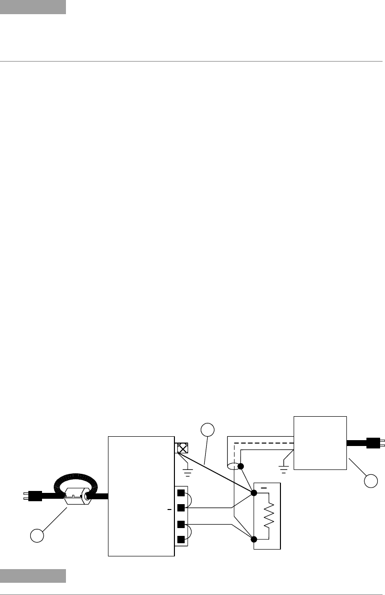
The following figure illustrates a typical situation where a load that
might otherwise be floating becomes grounded, thereby providing a
return path for any injected currents. In this case, the return path is
created by the low side of the scope probe, which is connected to the
load circuit common and also to the scope’s chassis. For this and
similar cases, the following steps by order of preference, will help
mitigate common mode current spikes appearing at the output when
the modular power system is turned on or off by the AC line switch:
1 Install the ferrite core on the power cord as described under
"Snap-On Core". This inserts impedance in the current path.
2 Install a separate “bonding” wire from the load’s common point,
to the ground terminal of the modular power system. This
provides a lower impedance path that helps direct injected
currents away from the DC output leads (and the sensitive load).
3 Break the return path through the external equipment. For
example, instead of the single-ended scope shown in the figure,
you can use a differential scope with a floating input or you can
connect an isolated measuring instrument to the load.
NOTE
Disconnecting the load from the output before switching the modular power
system on or off will always protect the load from common mode currents.
+S
+
-S
+
N6700 Modular
Power System
Scope
probe
1
3
2