


Installation 2
Series N6700 User’s Guide 25
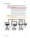
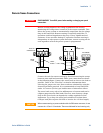
Connecting the Outputs
WARNING
SHOCK HAZARD Turn off AC power before making rear panel connections.
All wires and straps must be properly connected with the terminal block
screws securely tightened.
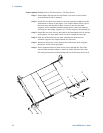
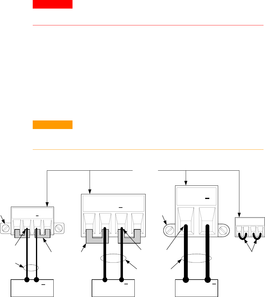
Disconnect the connector plug to make your wire connections. The
12A connector plug accepts wires sizes from AWG 12 to AWG 30. The
20A connector plug accepts wires sizes from AWG 10 to AWG 24. The
50A connector plug accepts wires sizes from AWG 6 to AWG 20. Wire
sizes smaller than AWG 20 are not recommended. Connect the load
wires to the + and - terminals. Connect the sense wires to the +s and
-s terminals. Sense jumpers are provided for local sensing.
Securely fasten all wires by tightening the screw terminals. Insert the
connector plug into the back of the unit. Secure the 12 A connector
by tightening the locking screws. A chassis ground binding post is
located next to the AC input connector for ground connections.
CAUTION
On power modules with the 50A sense connector, the +LS and –LS terminals
are ONLY used for local sense connections as illustrated. Do not connect these
terminals in any other way.
+S + -S
LOAD
TWIST LEADS
+
12 A
CONNECTOR
TIGHTEN
SCREWS
LOCKING
SCREW
+S + -S
LOAD
+
20 A CONNECTOR
+
LOAD
+
SENSE JUMPERS
INSTALLED FOR
LOCAL SENSING
INSERT WIRES
+S +LS -LS -S
SENSE JUMPERS
INSTALLED FOR
LOCAL SENSING
50A
SENSE
50 A
CONNECTOR
TWIST LEADS
INSERT WIRES
LOCKING
SCREW