


Installation 2
Series N6700 User’s Guide 29
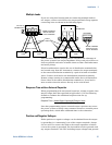
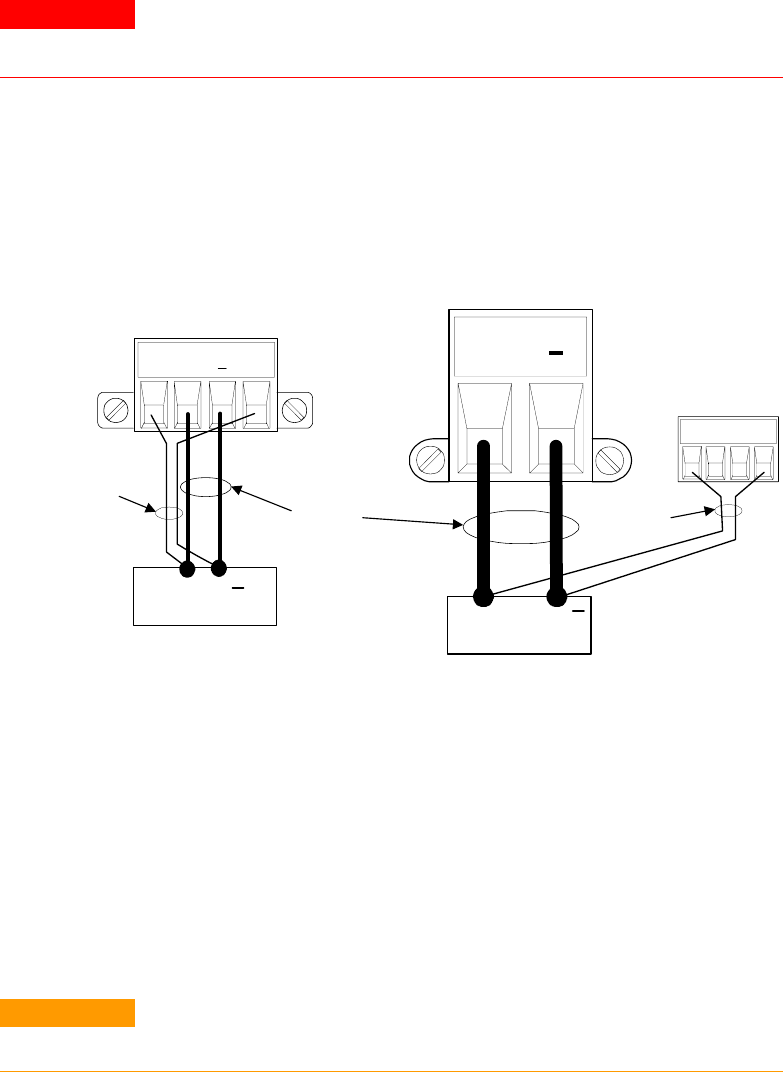
Remote Sense Connections
WARNING
SHOCK HAZARD Turn off AC power before making or changing rear panel
connections.
Remote sensing improves the voltage regulation at the load by
monitoring the voltage there instead of at the output terminals. This
allows the power system to automatically compensate for the voltage
drop in the load leads. Remote sensing is especially useful for CV
operation with load impedances that vary or have significant lead
resistance. It has no effect during CC operation. Because sensing is
independent of other power system functions, remote sensing can be
used regardless of how the power system is programmed.
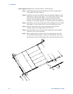
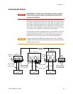
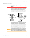
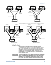
Connect the unit for remote sensing by first disconnecting the straps
between sense and load terminals. Make your connections as shown
in the following figure. Connect the sense leads as close to the load as
possible. Refer to the “Wire Size” section for information about
selecting the proper wire size. Best results are obtained by using the
shortest load leads practical. It is recommended to keep load leads
under 14.7 meters (50 feet) per lead because of inductance effects.
The sense leads carry only a few milliamperes of current and can be
a lighter gauge than the load leads. However, note that any voltage
drop in the sense leads can degrade the voltage regulation of the
instrument. Try to keep the sense lead resistance less than about
0.5Ω per lead (this requires 20 AWG or heavier for a 50 foot length).
CAUTION
When remote sensing on power modules with the 50A sense connector, do not
connect the +LS and –LS terminals. These are dedicated for local sensing only.
+S + -S
TWIST
LEADS
LOAD
+
+
LOAD
+
50A SENSE
TWIST
PAIR
50 A
CONNECTOR
12A & 20 A
CONNECTOR
TWIST
PAIR
+S +LS -LS -S