


Appendix B Using the Digital Port
90 Series N6700 User’s Guide
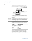
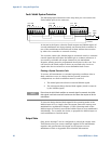
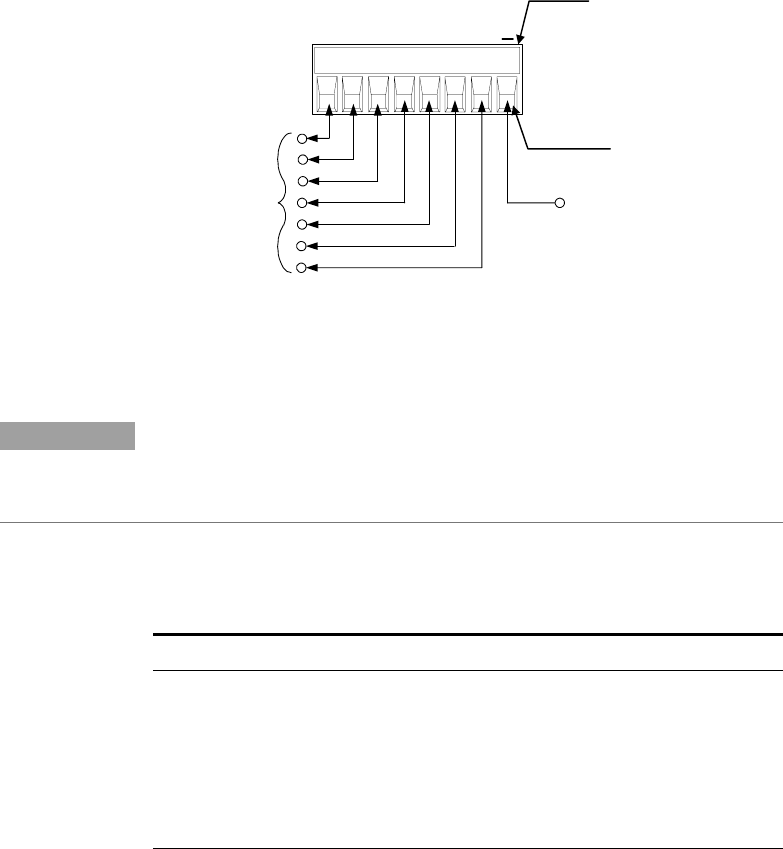
Digital Control Port
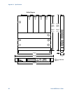
An 8-pin connector and a quick-disconnect connector plug are
provided on each instrument for accessing the five digital control
port functions.
The digital control connector accepts wires sizes from AWG 14 to
AWG 30. Note that wire sizes smaller than AWG 24 are not
recommended. Disconnect the connector plug to make your wire
connections.
NOTE
It is good engineering practice to twist and shield all signal wires to and from
the digital connectors. If shielded wire is used, connect only one end of the
shield to chassis ground to prevent ground loops.
The following chart describes the possible pin configuration for the
digital port functions. For a complete description of the electrical
characteristics of the digital I/O port, refer to Appendix A.
Pin Function Available configurable pins
Digital I/O and Digital In
Pins 1 through 7
External Trigger In/Out
Pins 1 through 7
Fault Out
Pins 1 and 2
Inhibit In
Pin 3
Output State
Pins 4 through 7
Common (⊥)
Pin 8
In addition to the configurable pin functions, the active signal
polarity for each pin is also configurable. When Positive polarity is
selected, a logical true signal is a voltage high at the pin. When
Negative polarity is selected, a logical true signal is a voltage low at
the pin.
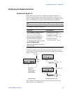
INSERT WIRES
TIGHTEN SCREWS
Input trigger
signal
Signal Common
Output trigger
signal, or
1 2 3 4 5 6 7
I
+ -